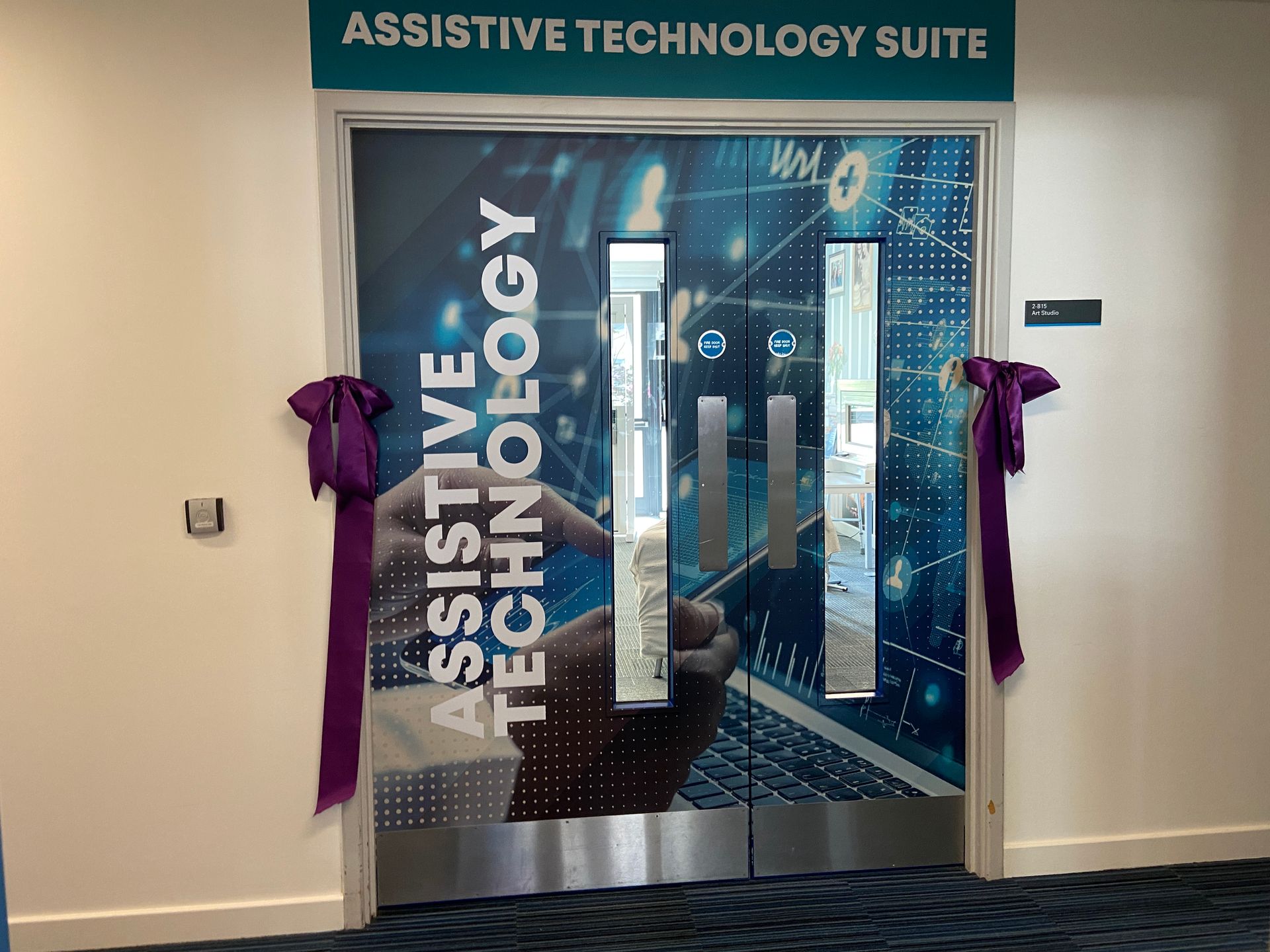
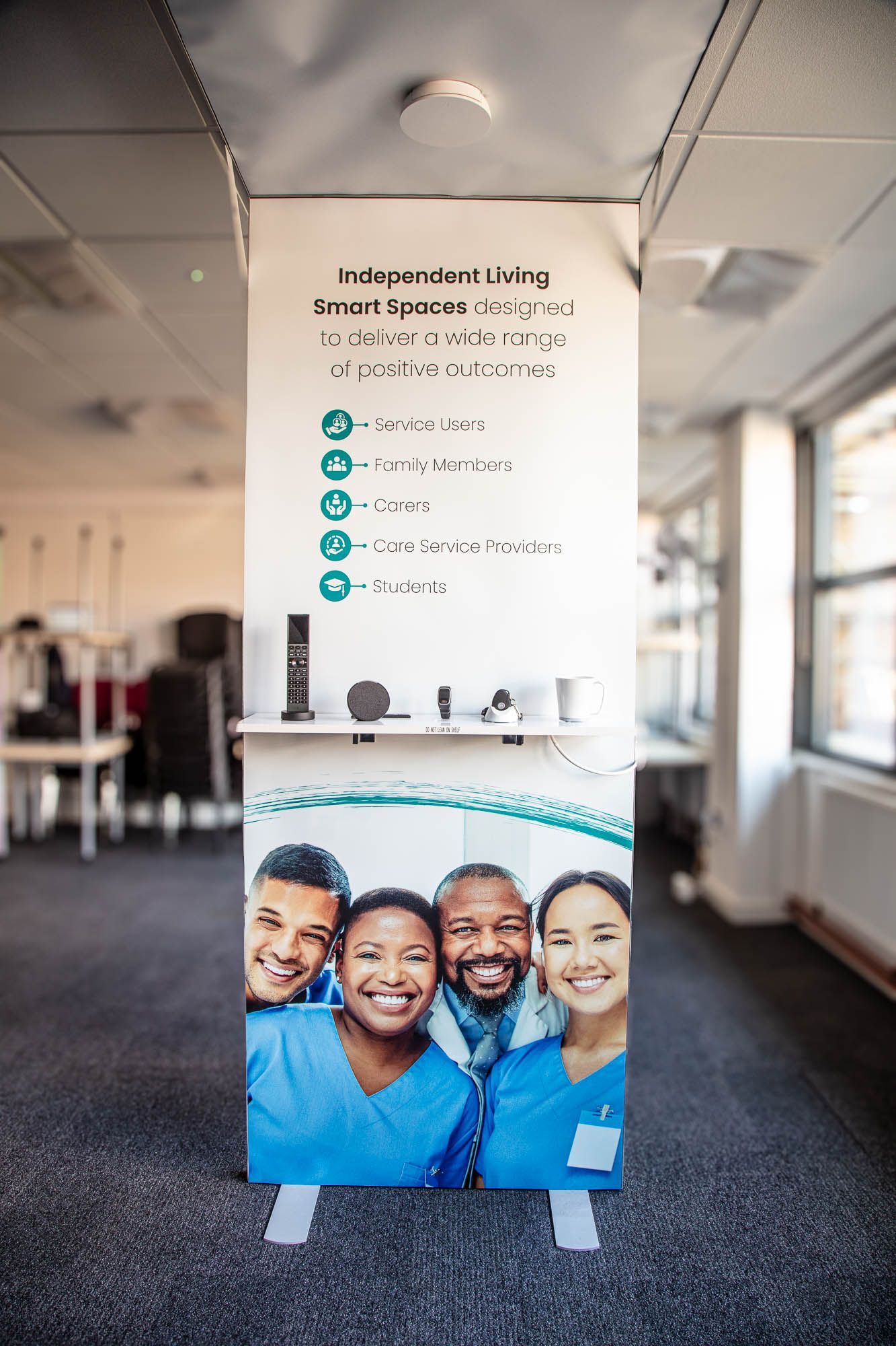
Independent Living Smart Spaces Demonstration Suite
An independent living technology immersive space to train the health and social care workers of the future
Background to project
The client project delivery team at East Kent College (EKC Group), as part of a consortium of 3 groups of colleges1 in the Kent region, approached us as they were preparing a grant application response to secure funding from the U.K. Government ‘Local Skills Improvement Fund’ (LSIF).
Part of the LSIF funding was aimed at supporting local further education (FE) providers to implement projects that would help address a skills gap in specific sectors. Within the Kent & Medway LSIF they identified that Health and Social Care was a focus sector.
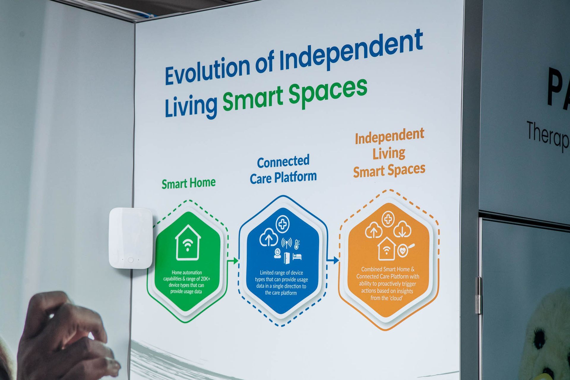
EKC Group were initially interested in understanding the ‘art of the possible’ with regards to the latest Assisted Living technologies that could be included within the future curriculums of their courses focused on Health & Social Care. During those earlier conversations EKC Group also expressed a desire to include within their grant application the creation of a demonstration room in six of their colleges, with a range of technologies, to allow their students to get hands-on during their studies. We put forward our in-house and unique concept of combining all the benefits of smart home solutions, a connected care platform and the ability to to create ‘Independent Living Smart Spaces’.
EKC Group were successful in their grant application and then asked us to assist in the helping with the creation of a two new curriculum streams as well as the installation of an ‘Independent Living Smart Spaces’ demonstration suite at six colleges.
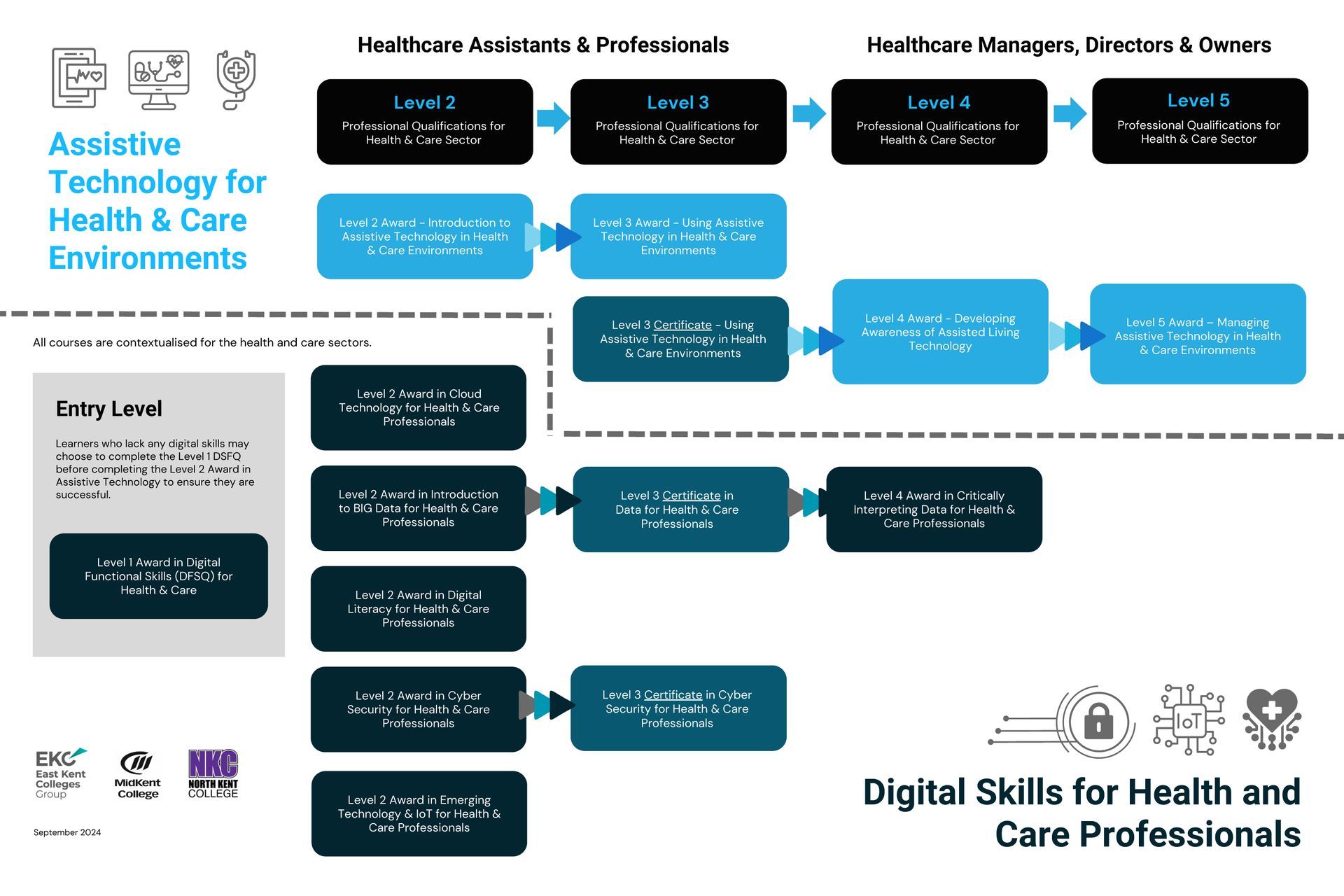
To assist with the creation of the two new curriculum streams we liaised with digital learning agency, the college engaged who separately, who were responsible for creating the curriculums. We helped the agency understand what the final demonstration suites would look like as well as the types of assisted living solutions they could provide. This allowed the agency to create curriculums that utilised the demonstration suites at their core. The two different curriculum streams were:
a) ‘Assistive Technology for Health & Care Environments’
b) ‘Digital Skills for Health and Care Professionals’
With Level 2 to Level 5 courses aimed at both Healthcare Assistants & Professionals as well as Healthcare Managers, Directors & Owners.
Learn more about the available courses: https://www.ekcgroup.ac.uk/collaborate-with-us/supporting-innovation-in-health-and-care/
1 (East Kent Colleges Group, MidKent College and North Kent College)
Outcome first approach
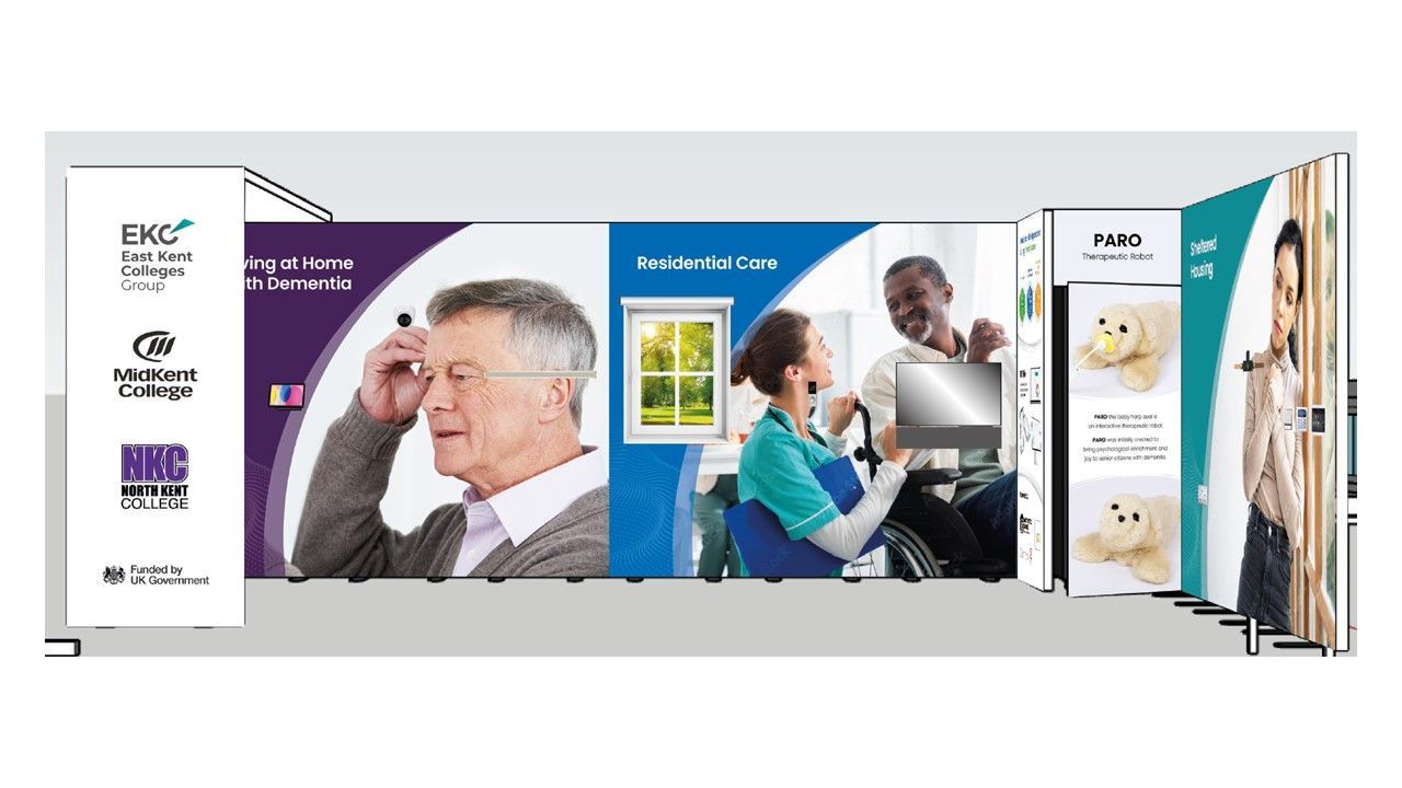
With regards to the demonstration suites, we took an approach of leading with a ‘outcome first’ approach i.e., we focused on the possible outcomes/solutions that the smart home technology could help deliver for people and the technology itself was purely an enabler.
We decided to focus the outcomes around 3 different personas/scenarios:
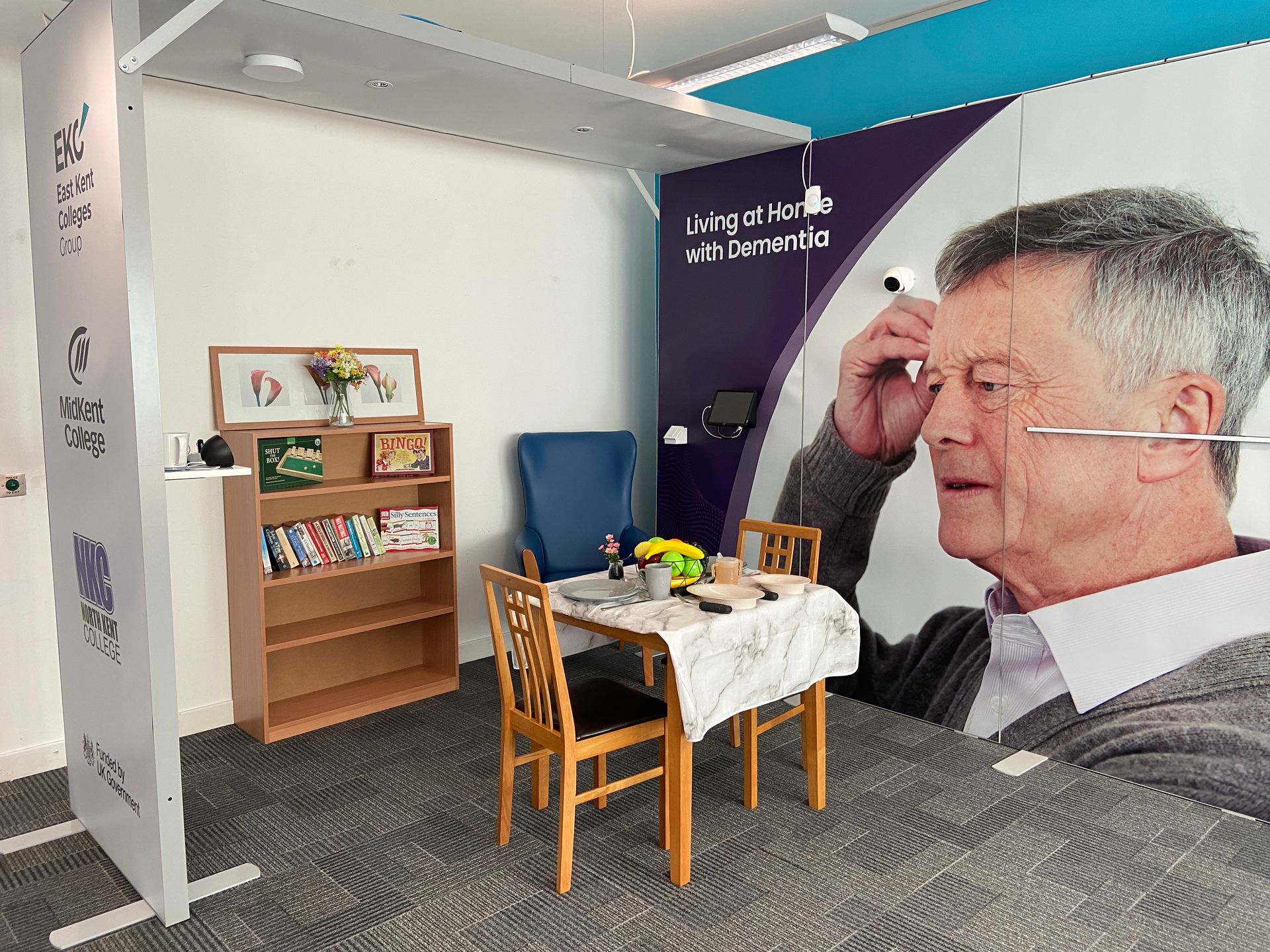
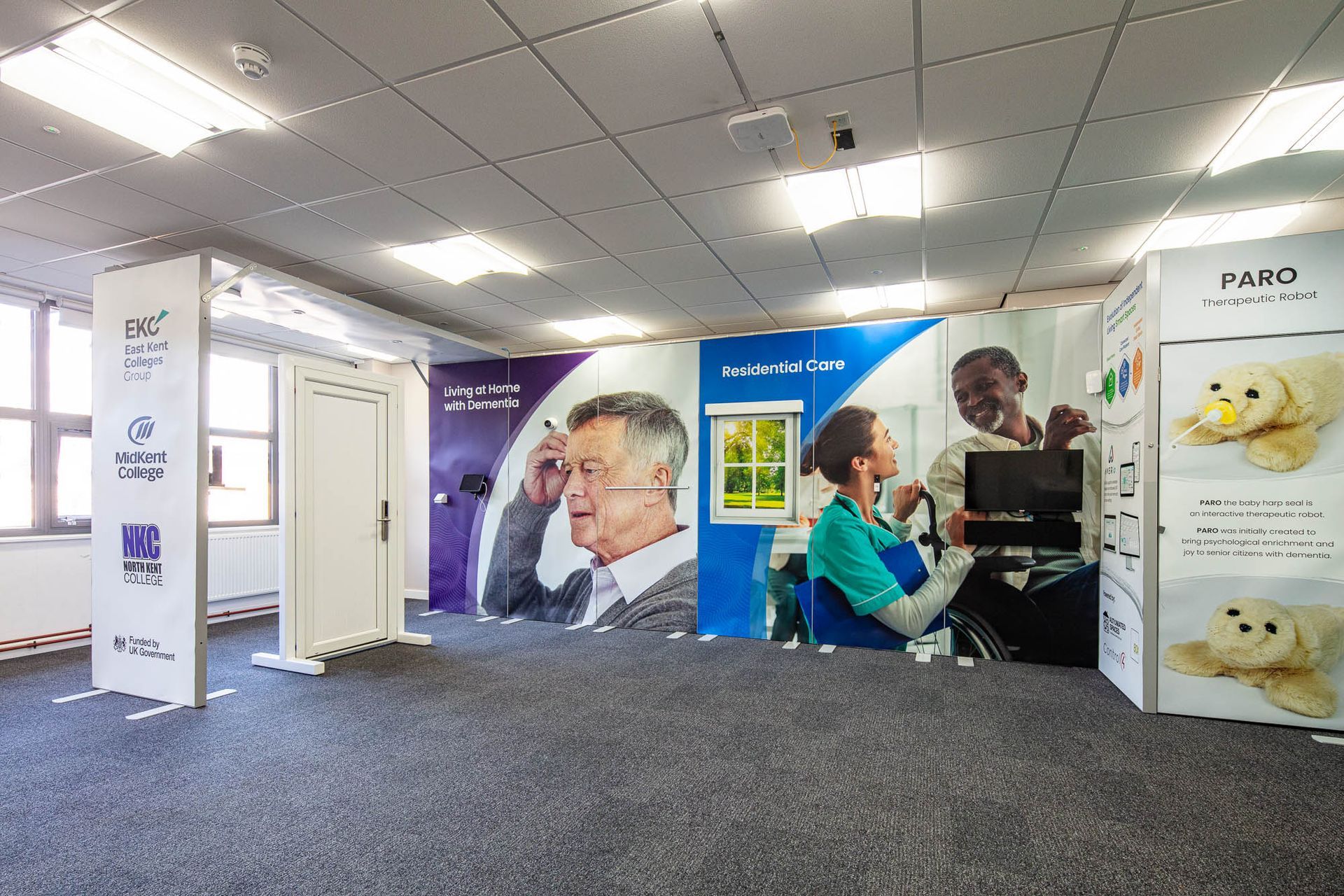
- Person living at home with dementia
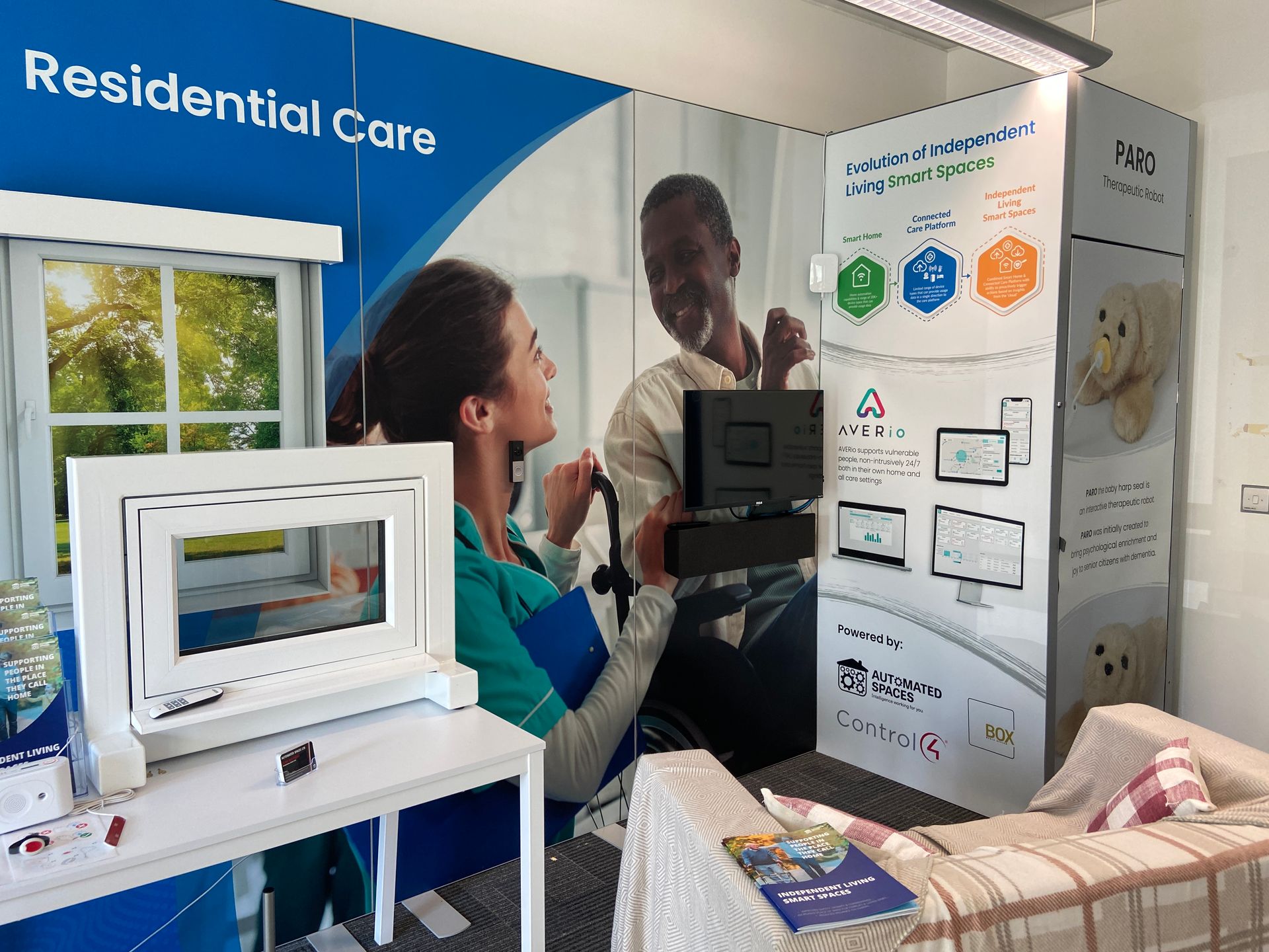
- Residential care setting
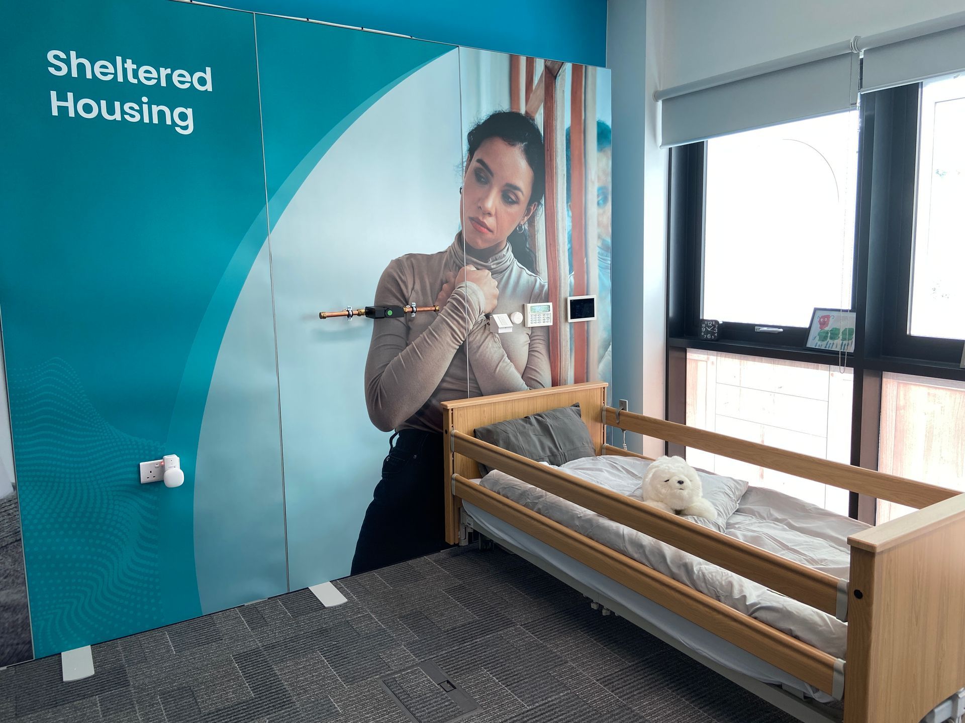
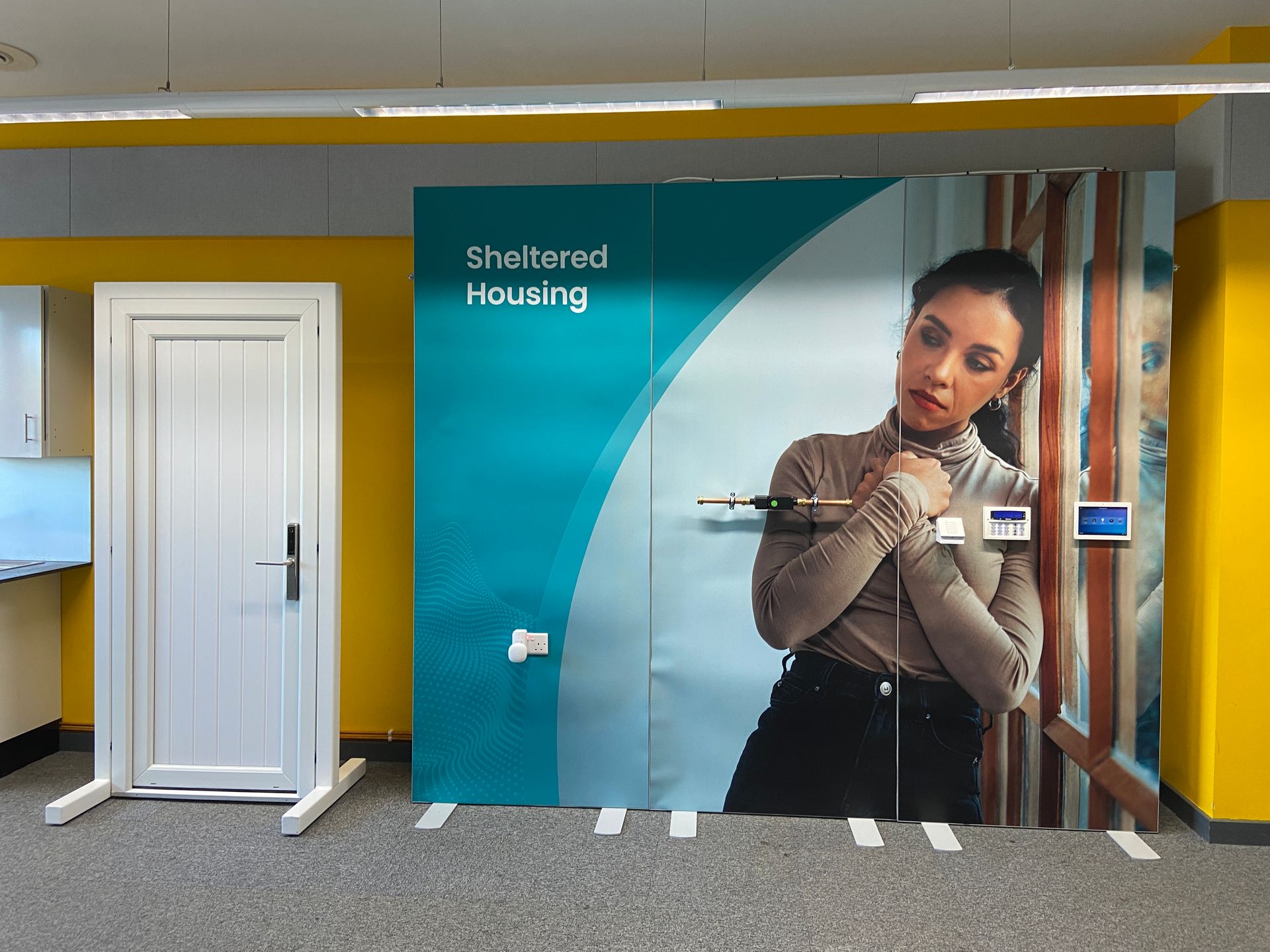
- Sheltered housing setting
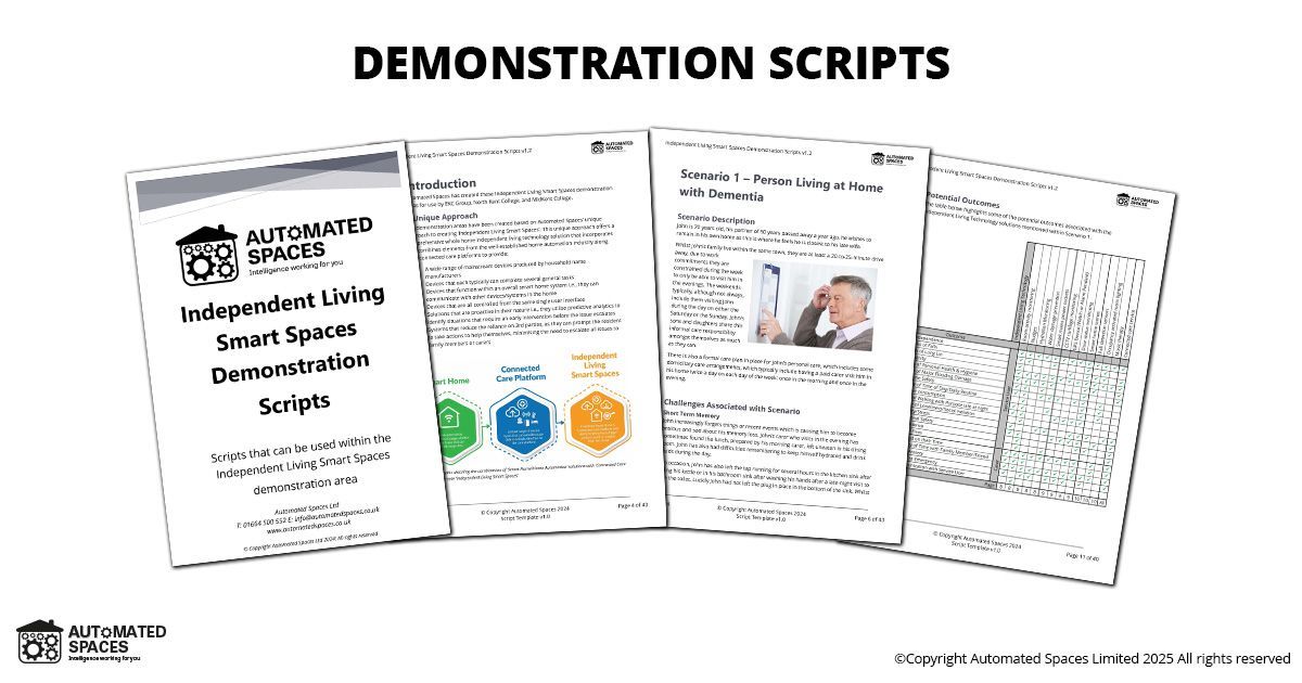
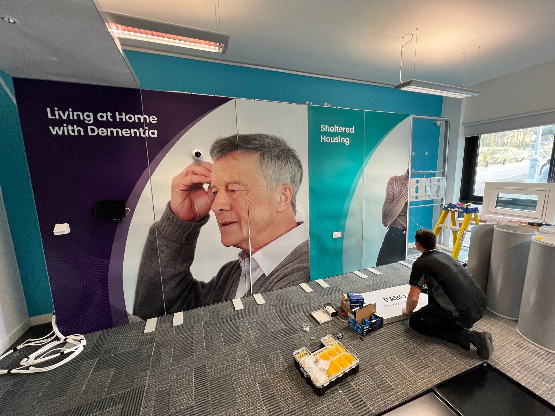
For each of these scenarios we created a backstory that included an overview of the person/scenario, a summary of the challenges faced by the people within that scenario and then identified potential solutions that could be provided using a combination of smart home technologies and a connected care platform.
As an example, for the ‘Person living at home with dementia’ scenario we created a persona of a gentleman called John. John is 70 and lives alone in his home after his partner recently passed away. We outline numerous challenges that John faces ranging from short term memory issues, incidents of purposeful wandering, confusing day and night, high risk of falls and long-term memory issues. We then were able to identify solutions to all these specific challenges that could be delivered using the various smart home technologies deployed into the demonstration suite combined with an external connected care platform.
This ‘outcome first’ approach would allow the Health & Social Care teachers in the colleges to focus on describing, to the people receiving the tour of the demonstration suite, the potential outcomes/solutions that could be delivered as part of a more relatable real-world example e.g., for a person living at home with dementia. It meant that the teachers didn’t need to become experts in smart home technology instead they could stay within their comfort zones of being subject matter experts within the Health & Social Care arena.
Contents of this case study
Contents of this case study:
- Site survey and project timeframes
- Proposed room layouts
- Design documentation
- 1st fix phase
- 2nd fix phase
- 3rd fix phase
- Finished demonstration suites
- Installed equipment
- Summary of installed equipment
If you would like to discuss how we could help you with your specific project, feel free to call us +44(0)1664 500552
Or click the following button to use our online consultation booking tool
Site survey and project timeframes
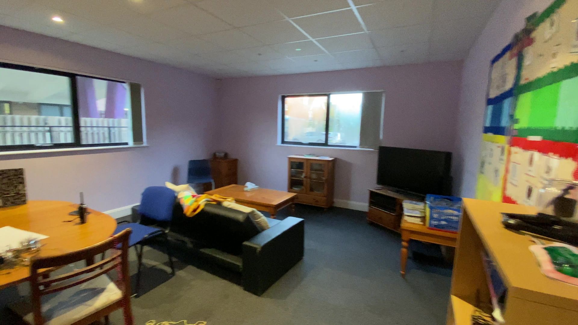
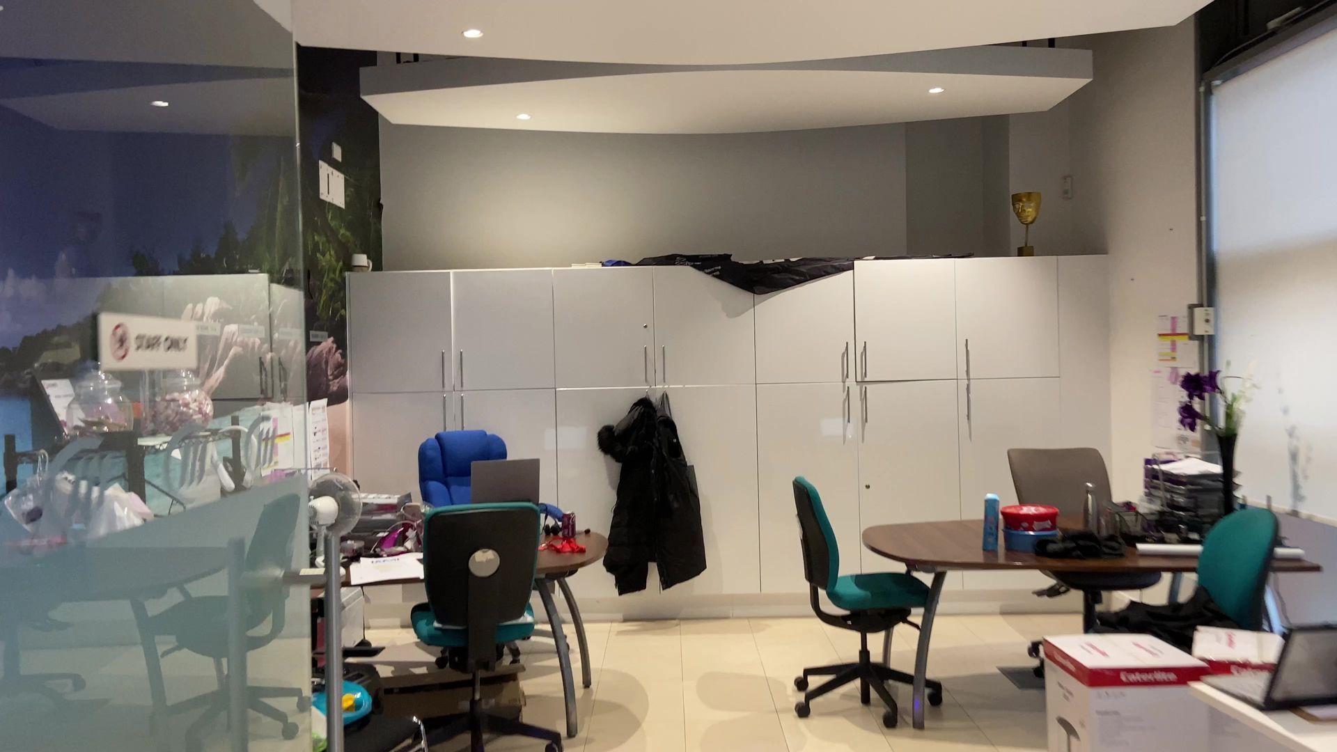
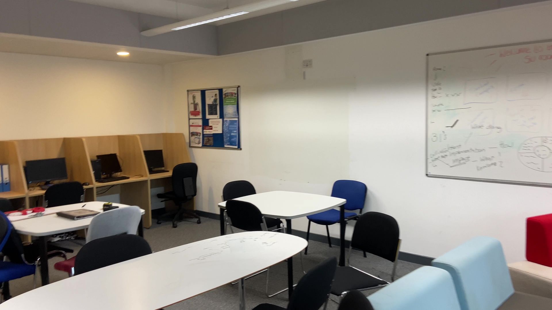
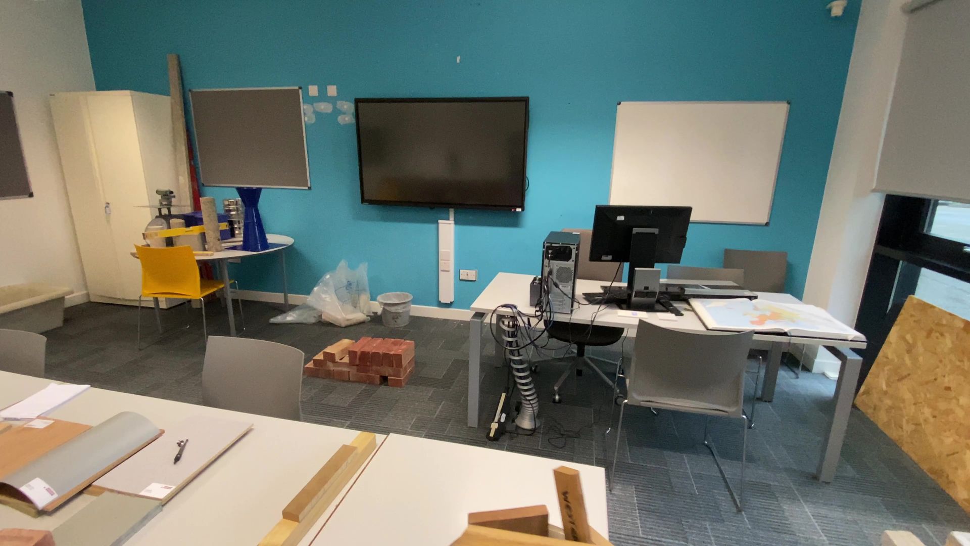
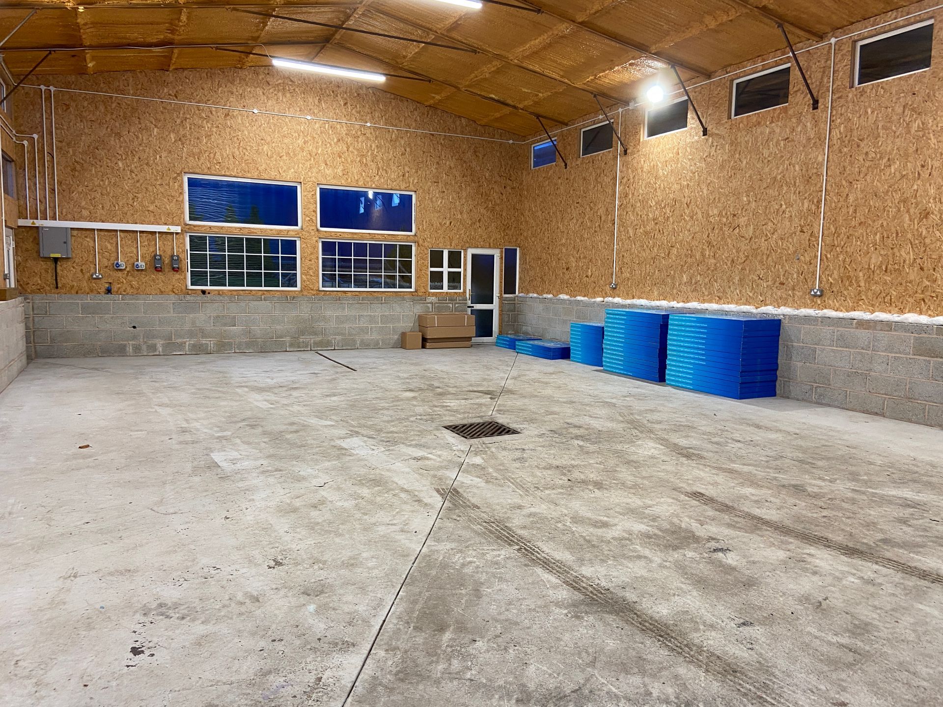
Very quickly after securing grant funding, with the very short timeframes to deliver the project (less than 3 months), it became apparent that we would need to find a solution to allow us to install the equipment into the 6 different college locations in a time efficient manner. After we conducted a thorough site survey at each college location it was identified that whilst the equipment to be installed was the same at each site the actual room where it would be located all had their own individual specific characteristics, layouts, dimensions and challenges.
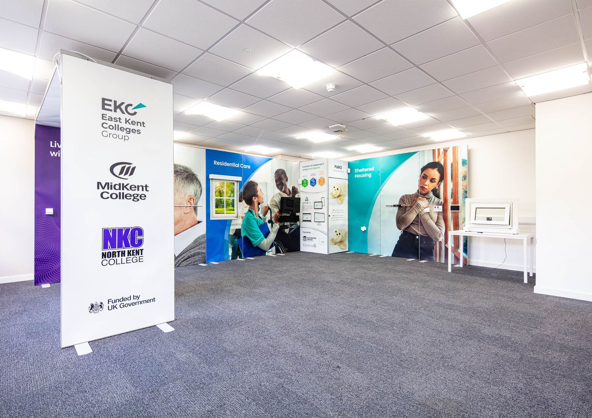
We identified we could provide a better experience for visitors by creating a professional looking demonstration environment whilst at the same time also significantly de-risking the project by utilising an exhibition space display systems for the suites. The exhibition space display system could be custom designed and built offsite with all the relevant equipment then installed within the internals of the units. The pre-wire and initial installation of equipment would be completed at our workshop. We would then bring the partially constructed exhibition space display systems and pre-wire looms to site for final installation.
This approach meant that impact of modifications to the project, such as due the differences between the physical rooms, could be kept to making minor changes to the exhibition space display system e.g., Folkestone college had a very low ceiling height of 2300mm compared to a typical height of 2600mm in the other colleges. The standard height of the exhibition space display system units was 2500mm, therefore we were able to get the exhibition space display system supplier to custom make the units for Folkestone college to be 2200mm tall at their factory before shipping to our workshop.
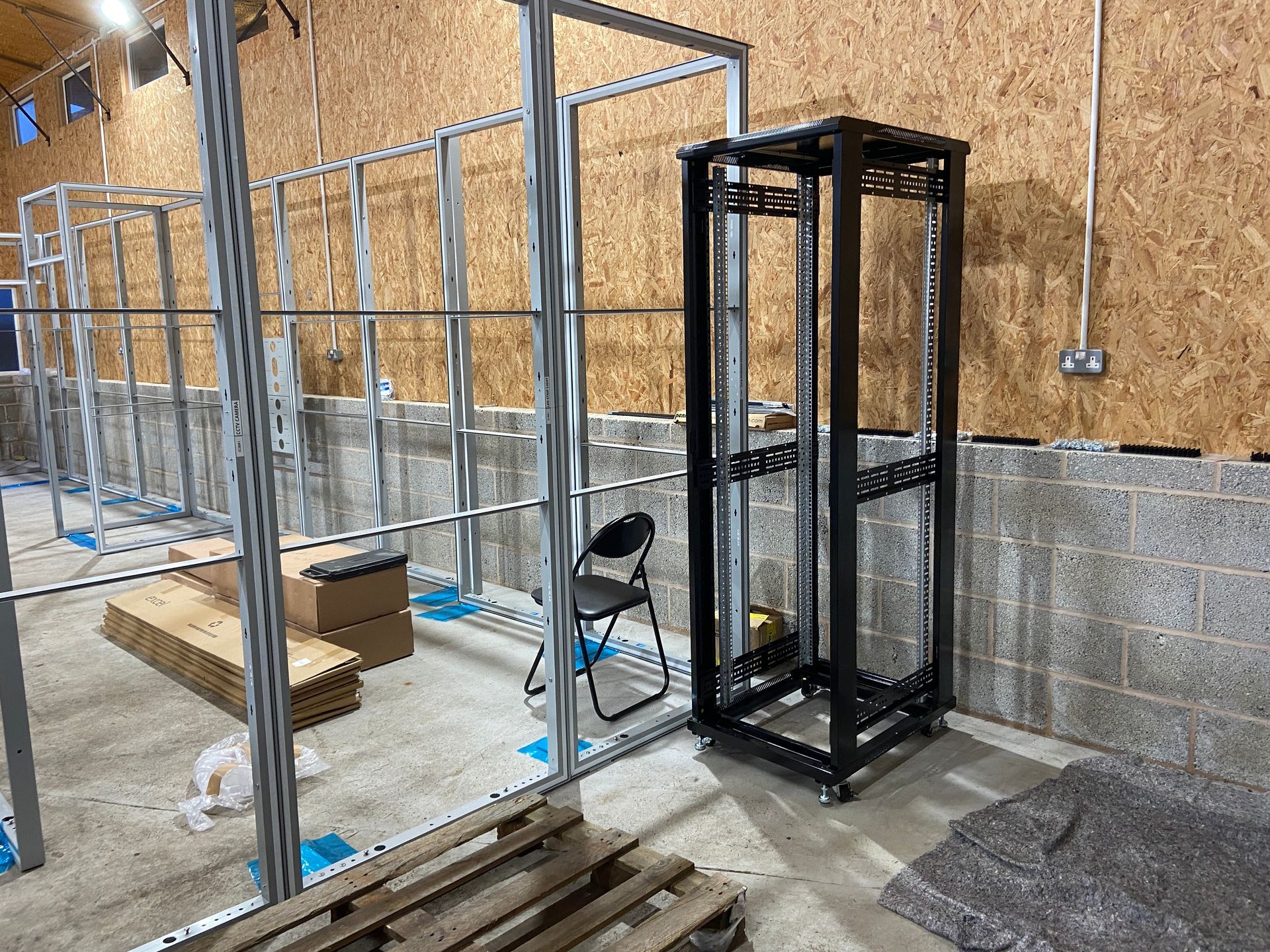
We also identified that there wasn’t any available space within any of the college existing server rooms to allow us to locate our rack mounted equipment. Therefore, within the design of the exhibition space display systems we also incorporated a cupboard to hide our server rack within the actual demonstration suite room. Then from this exhibition space display systems cupboard all the relevant pre-wire cables run through the internals of the display systems to their relevant position.
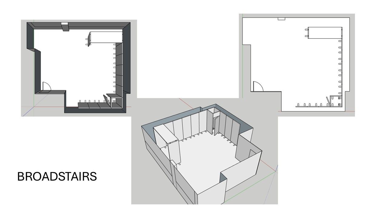
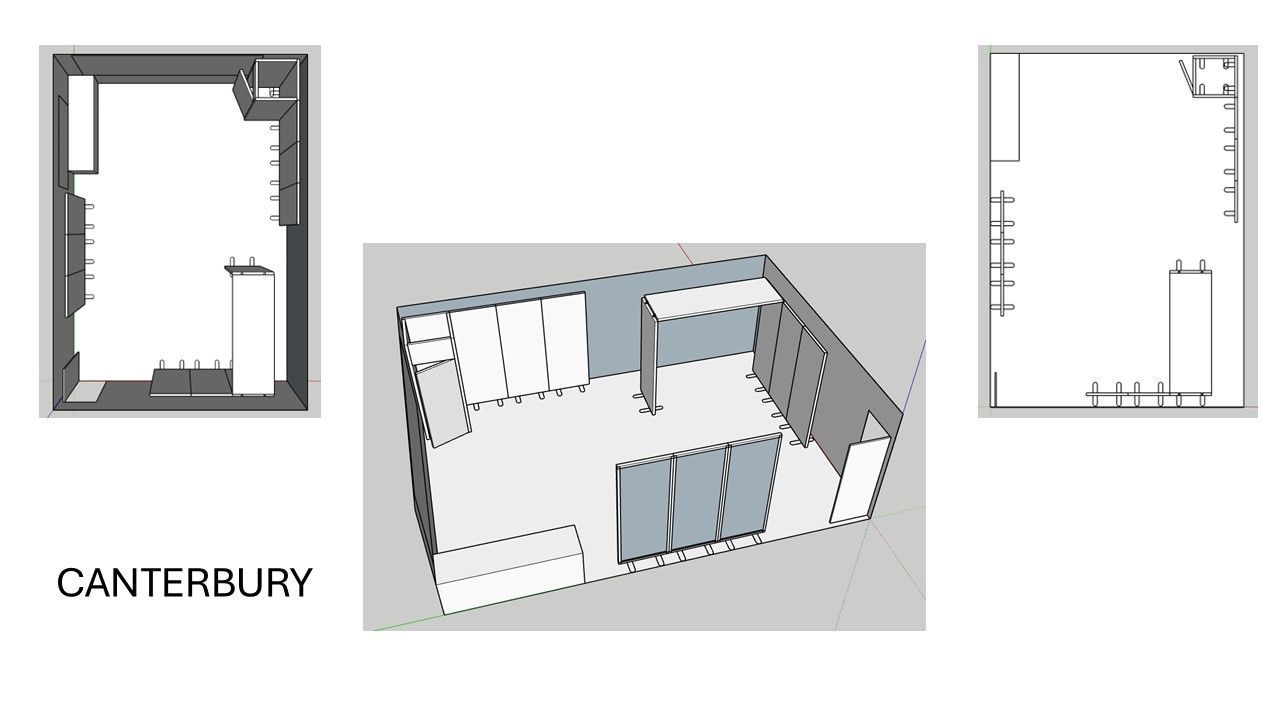
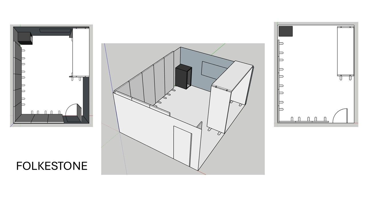
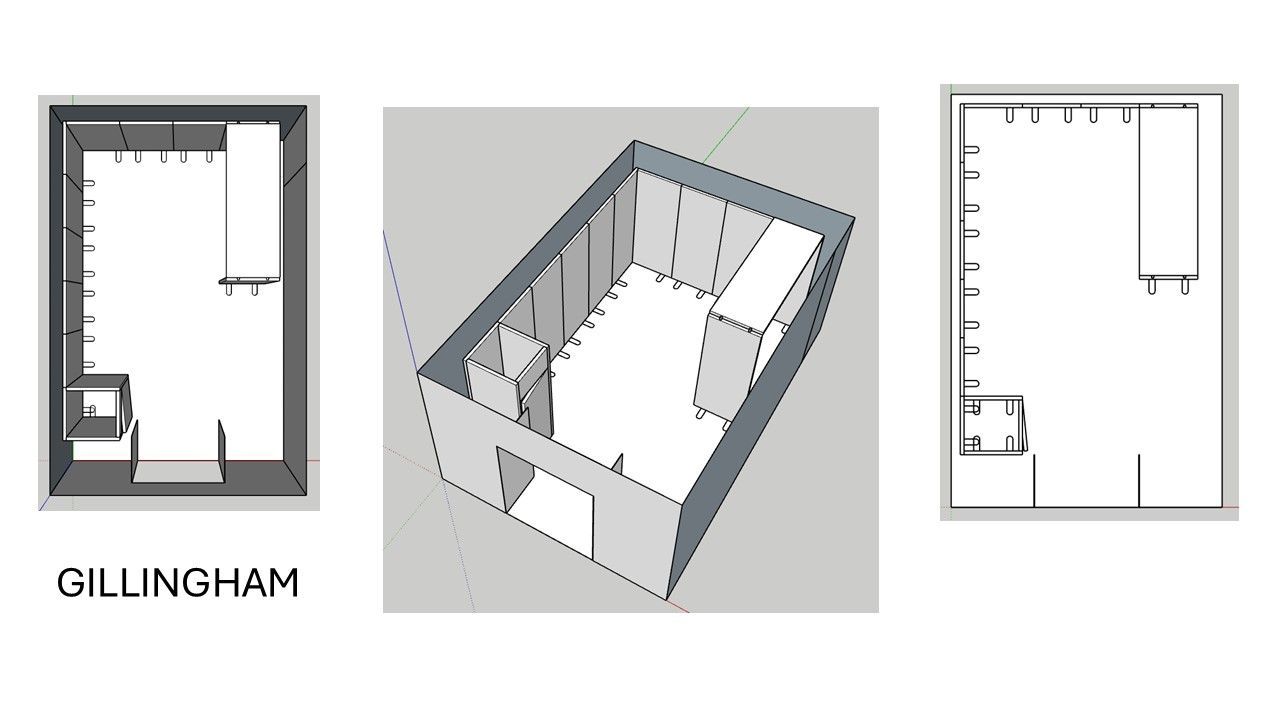
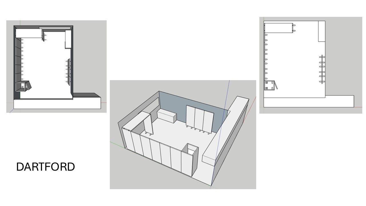
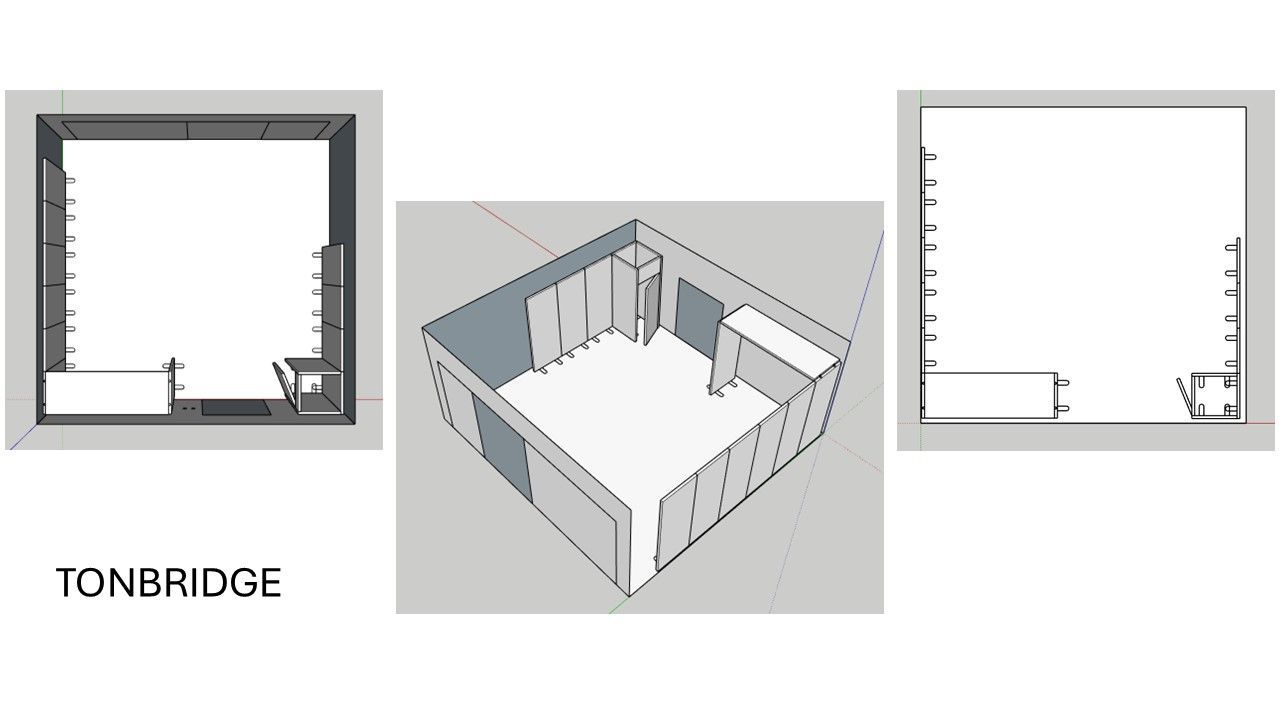
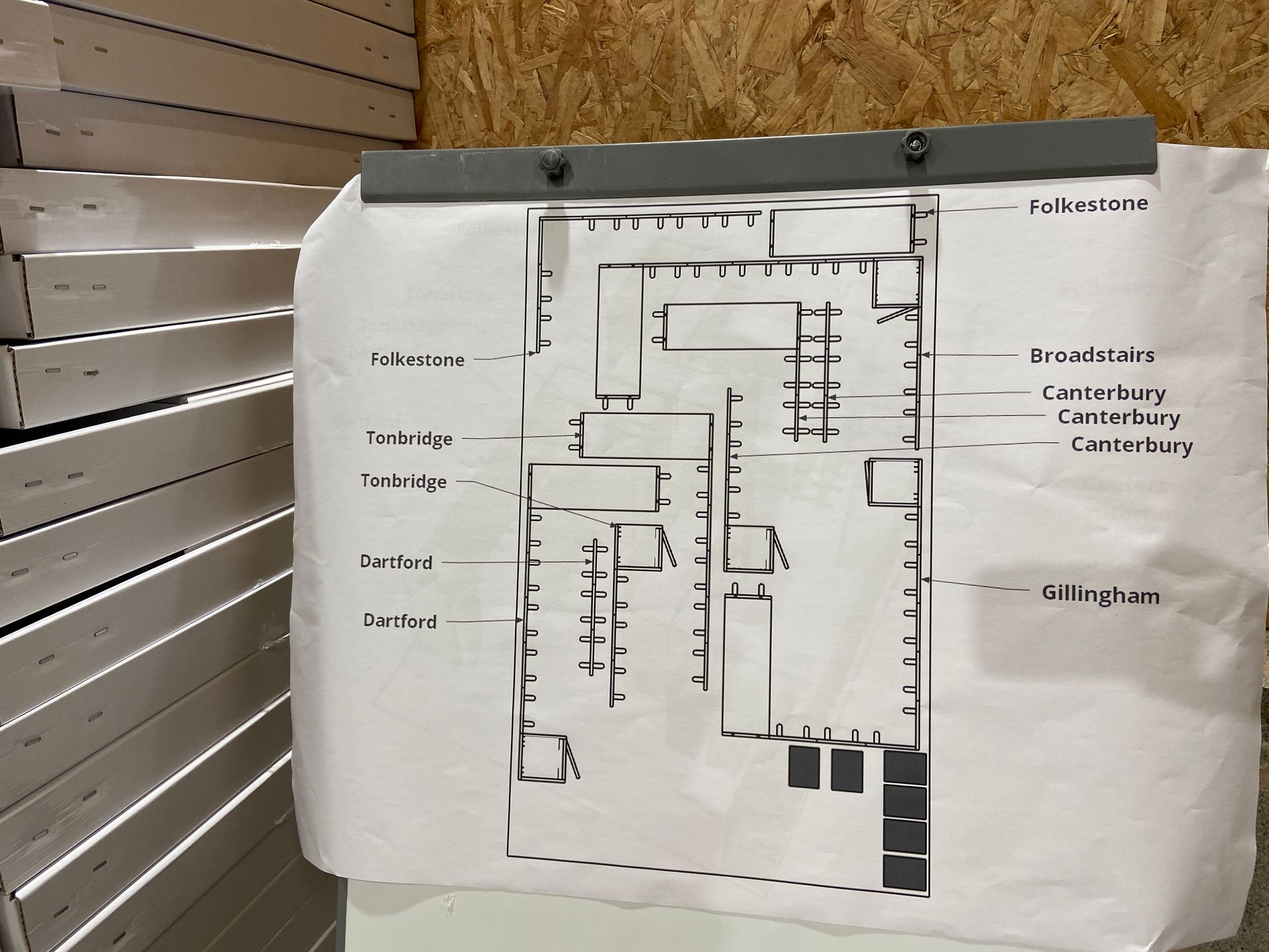
Proposed room layouts
To help the client better visualise what the final immersive spaces might look like we created each of the separate 6 rooms in a 3D modelling tool.
This allowed us to establish the best orientation of the exhibition panels as well as identify any potential clashes with physical infrastructure in the room e.g., suspended lights, etc.
The visualisations also allowed the department staff at each college to be introduced to the proposed plans very early in the design phase.
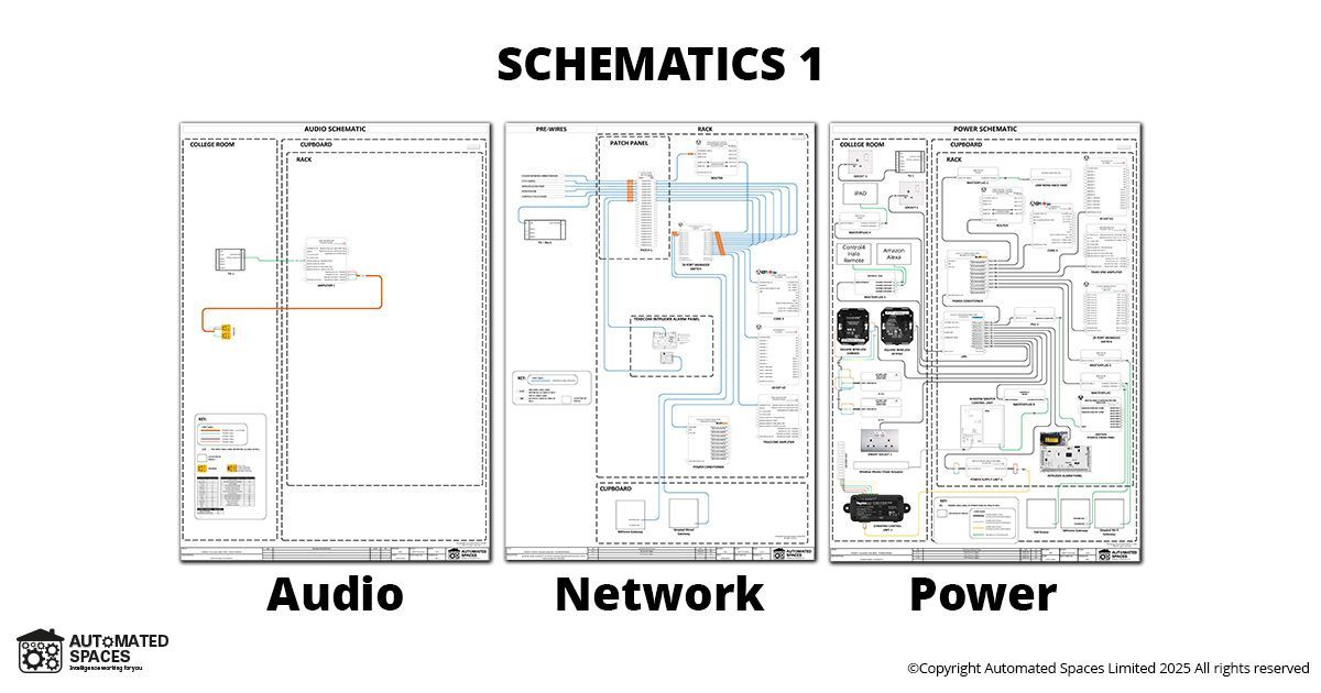
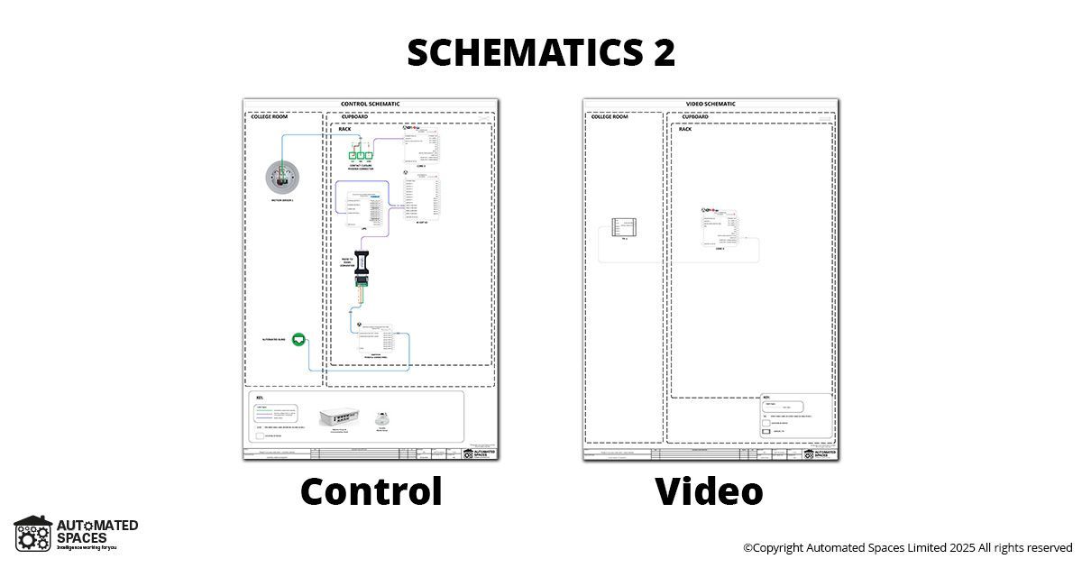
Design documentation
Once the persona examples and proposed room layouts had been agreed we then began on the technical design including some of the following documents:
- Schematics for:
- Network
- Power
- Audio
- Video
- Control
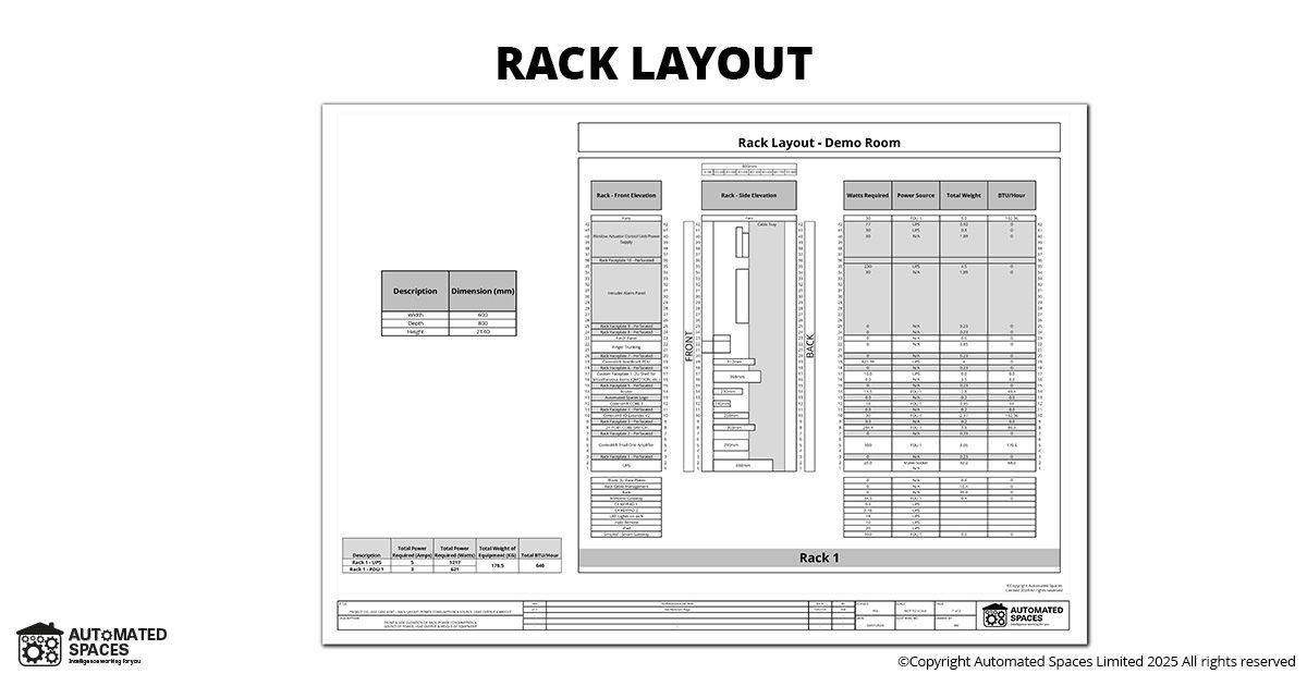
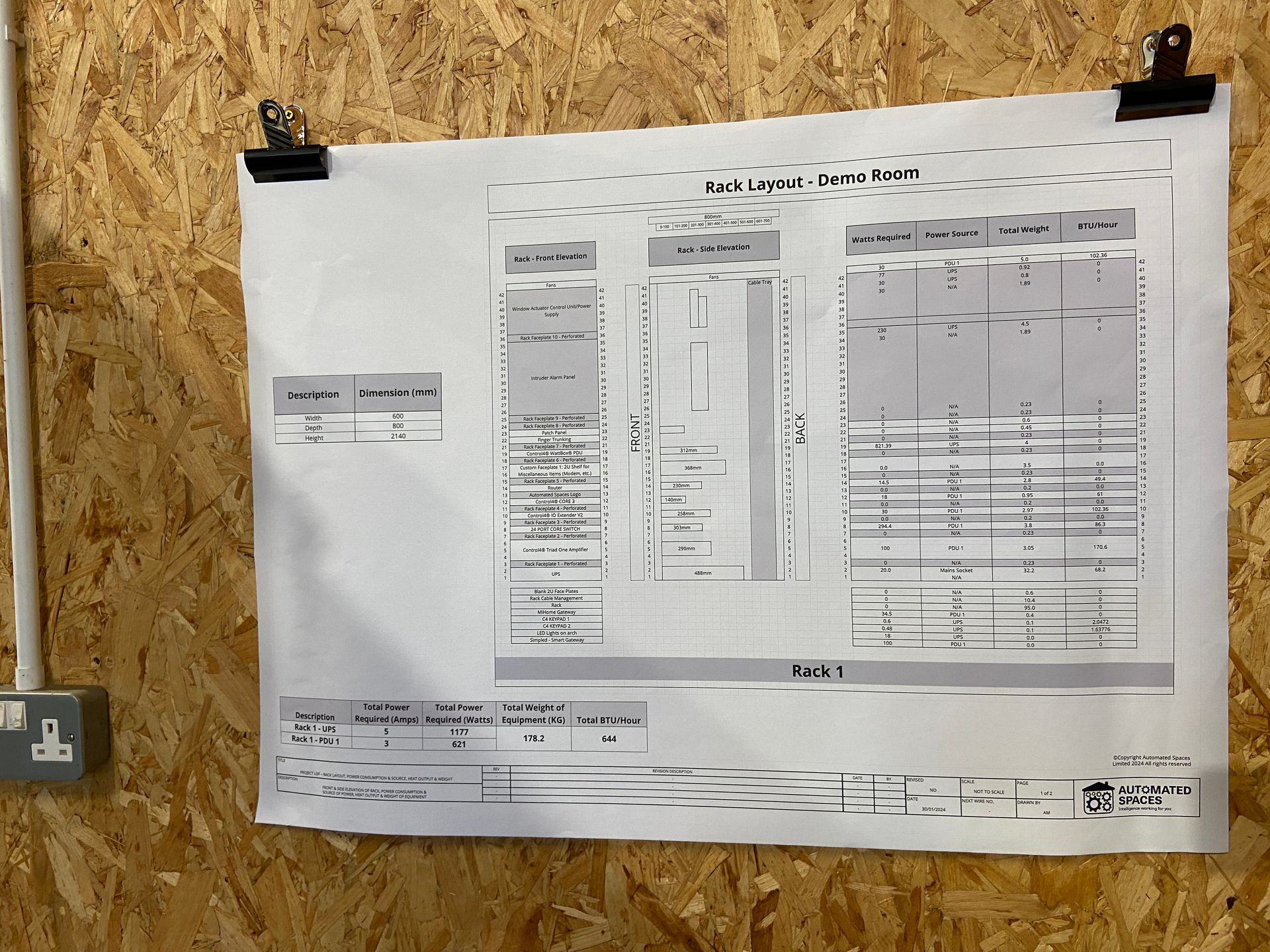
- Rack layouts
After drafting the technical documentation, to assist with our outcome-based approach we created various handover documentation for the teachers to use as guides and prompts whilst they are using the demonstration suites.
We were careful to provide ‘non-technical’ descriptions of the various outcomes/solutions to the various challenges and used ‘Plain English’ descriptions.
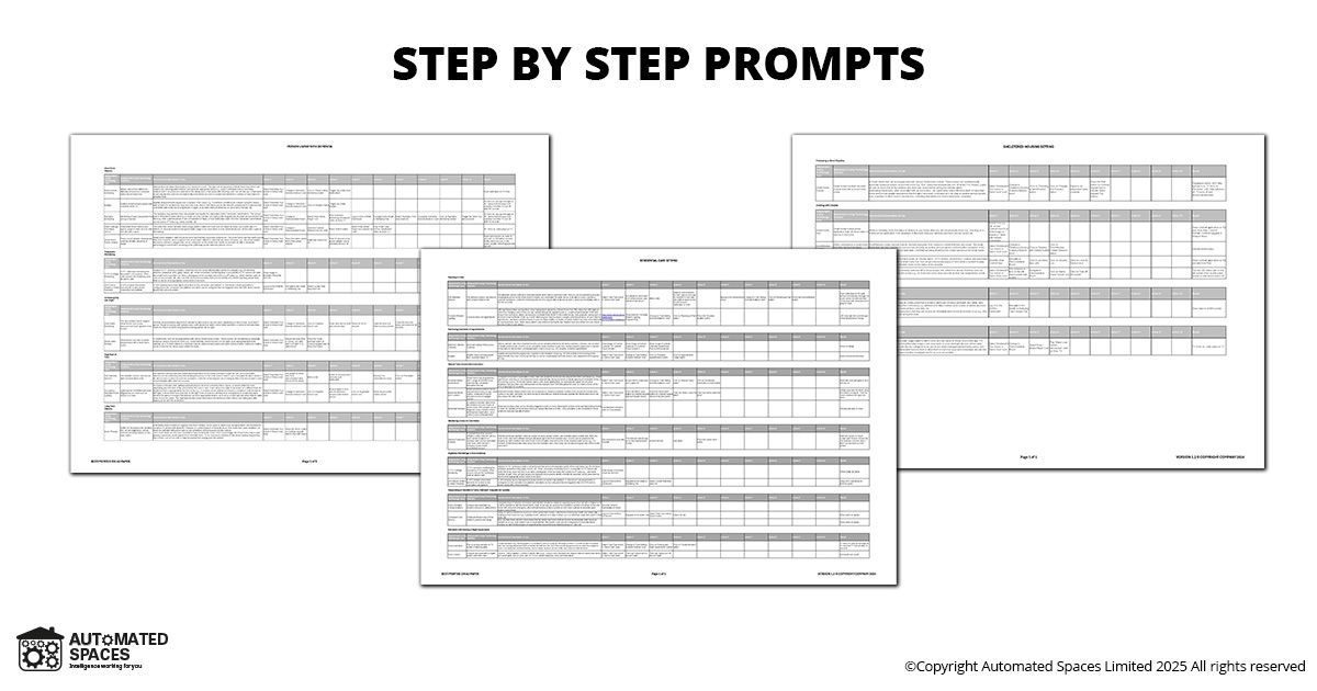
We also provided ‘step by step’ instructions to allow the teachers to confidentially be able to demonstrate all the available outcomes for all 3 scenarios.
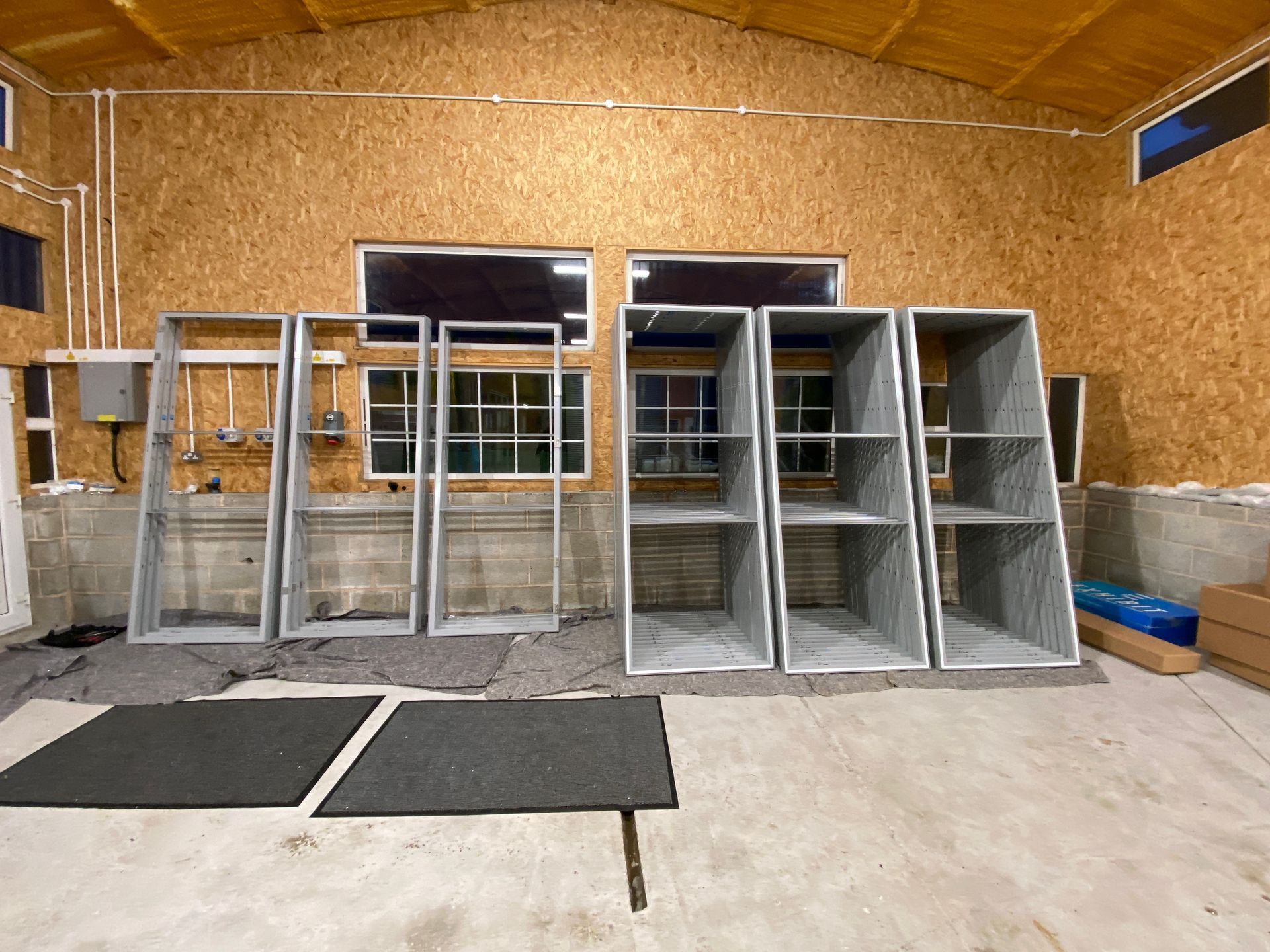
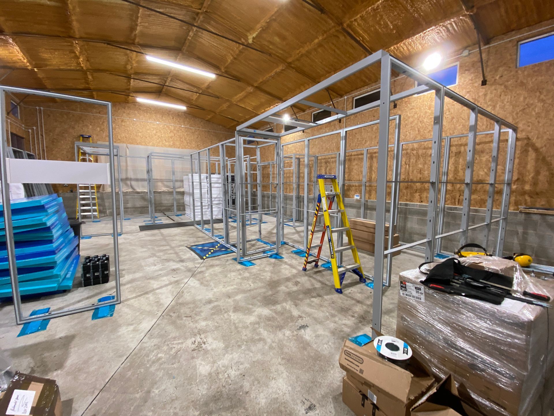
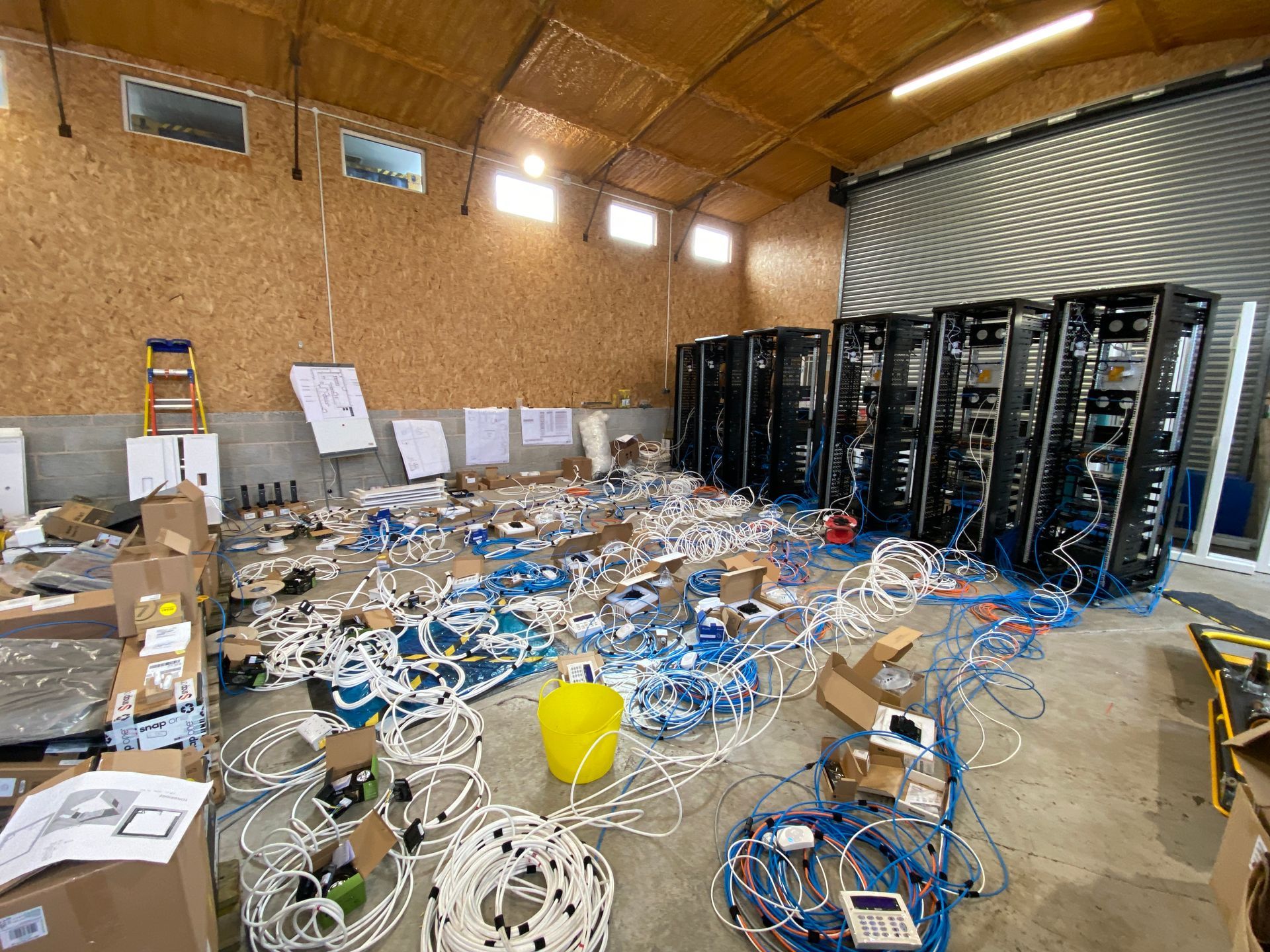
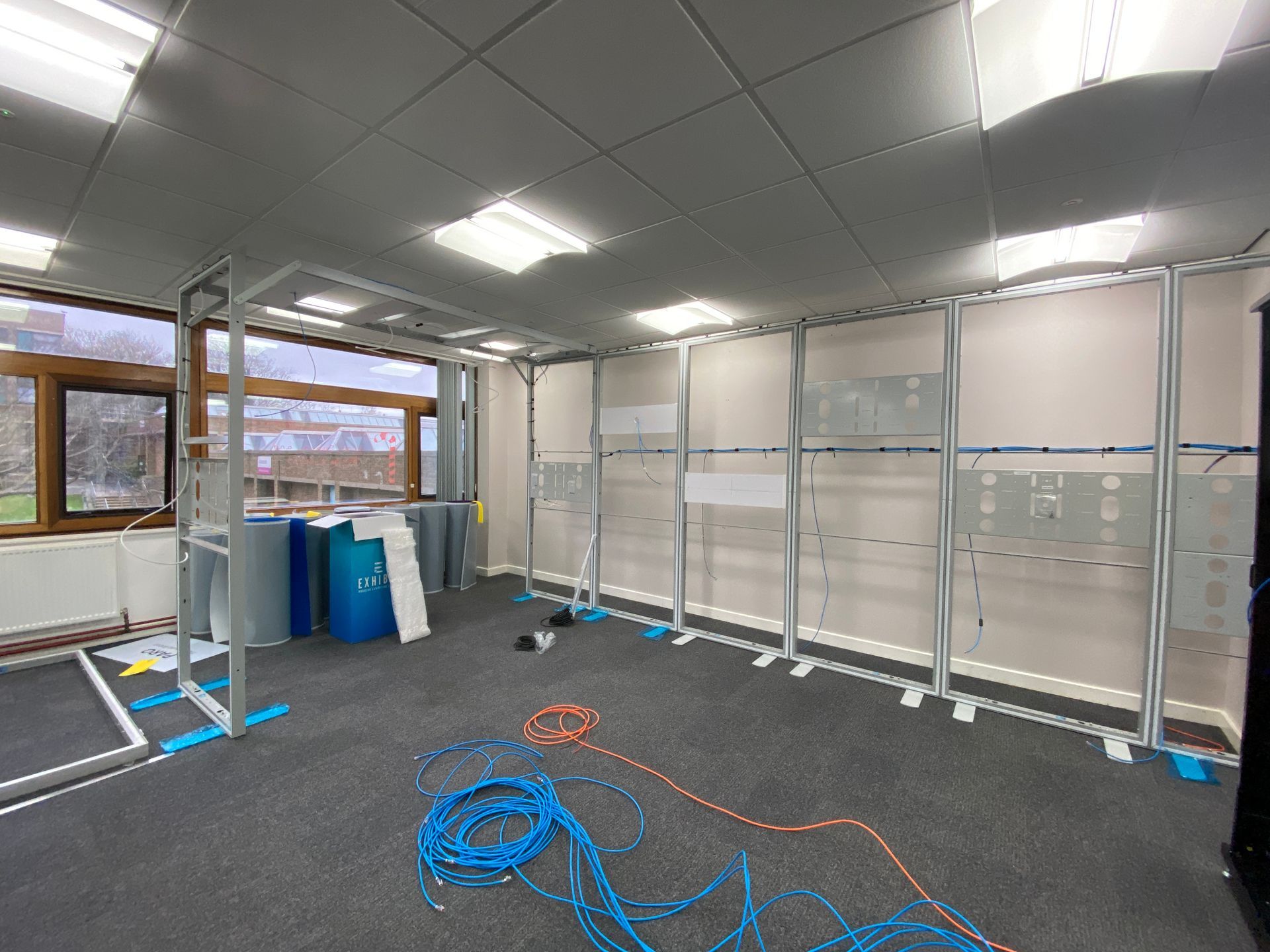
1st fix phase
As we were installing the equipment onto exhibition space display systems this meant that we could prebuild the relevant panels at our workshop. This meant we could optimise the installation process as we could test fit all the panels and equipment mounting locations in advance of the actual onsite installation phase.
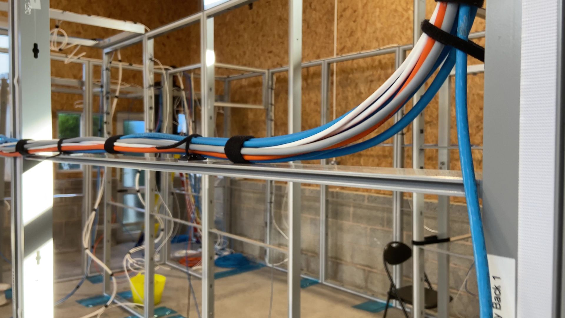
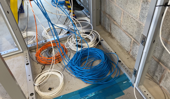
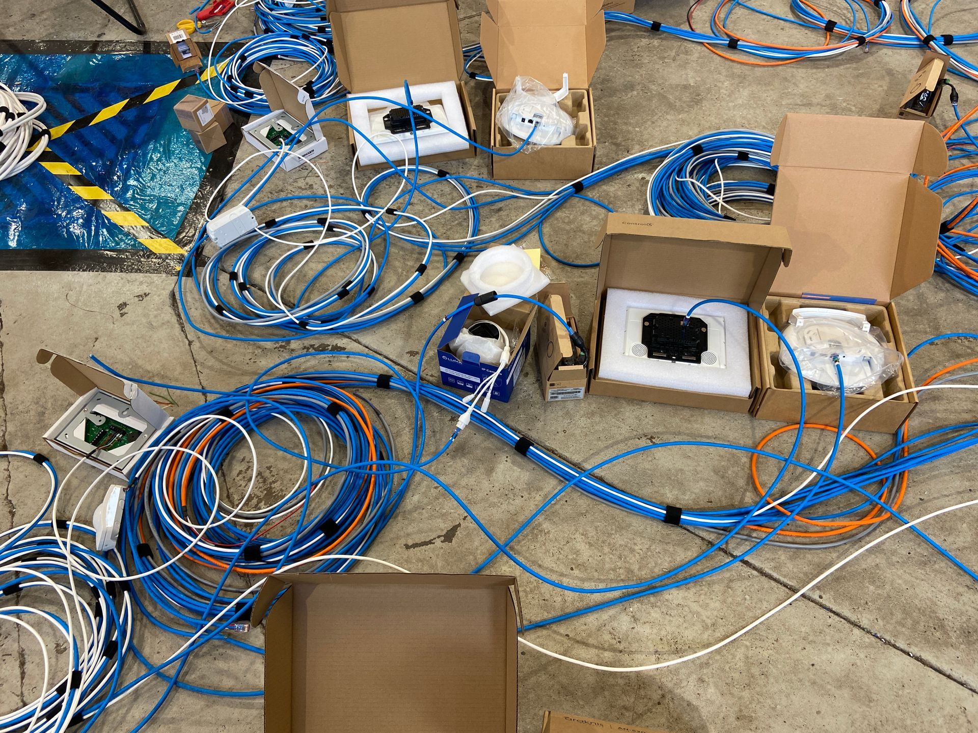
This also allowed us to identify the proposed cable runs from the relevant server rack location to each individual piece of equipment. As such we were able to form the following distinct cables looms:
- Power cable loom
- Non-power cable loom, including:
- Network cables
- Intruder alarm cables
- Speaker cables
- HDMI cables
- Control cables
All the cables were thoroughly continuity tested after initially being made up at our workshop and prior to soak testing the equipment at our workshop. This meant we only went to site with known functioning pre-made and pre-labelled cables.
2nd fix phase
The 2nd Fix construction phase, at a client site, is typically when the site environment is the dustiest, has lots of sources of water present, has the most inconsistent power provision with frequent planned and unplanned power outages and has the highest amount of physical other trades people onsite moving around materials and tools.
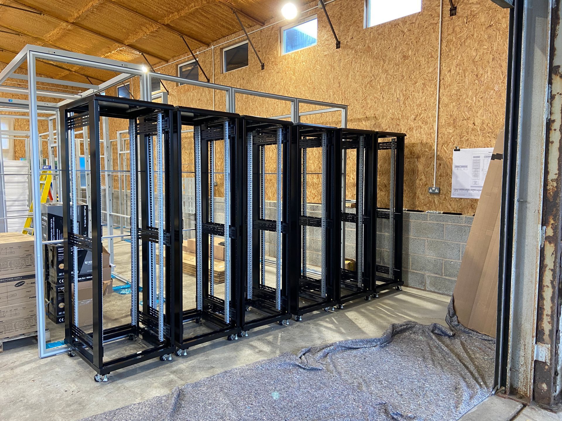
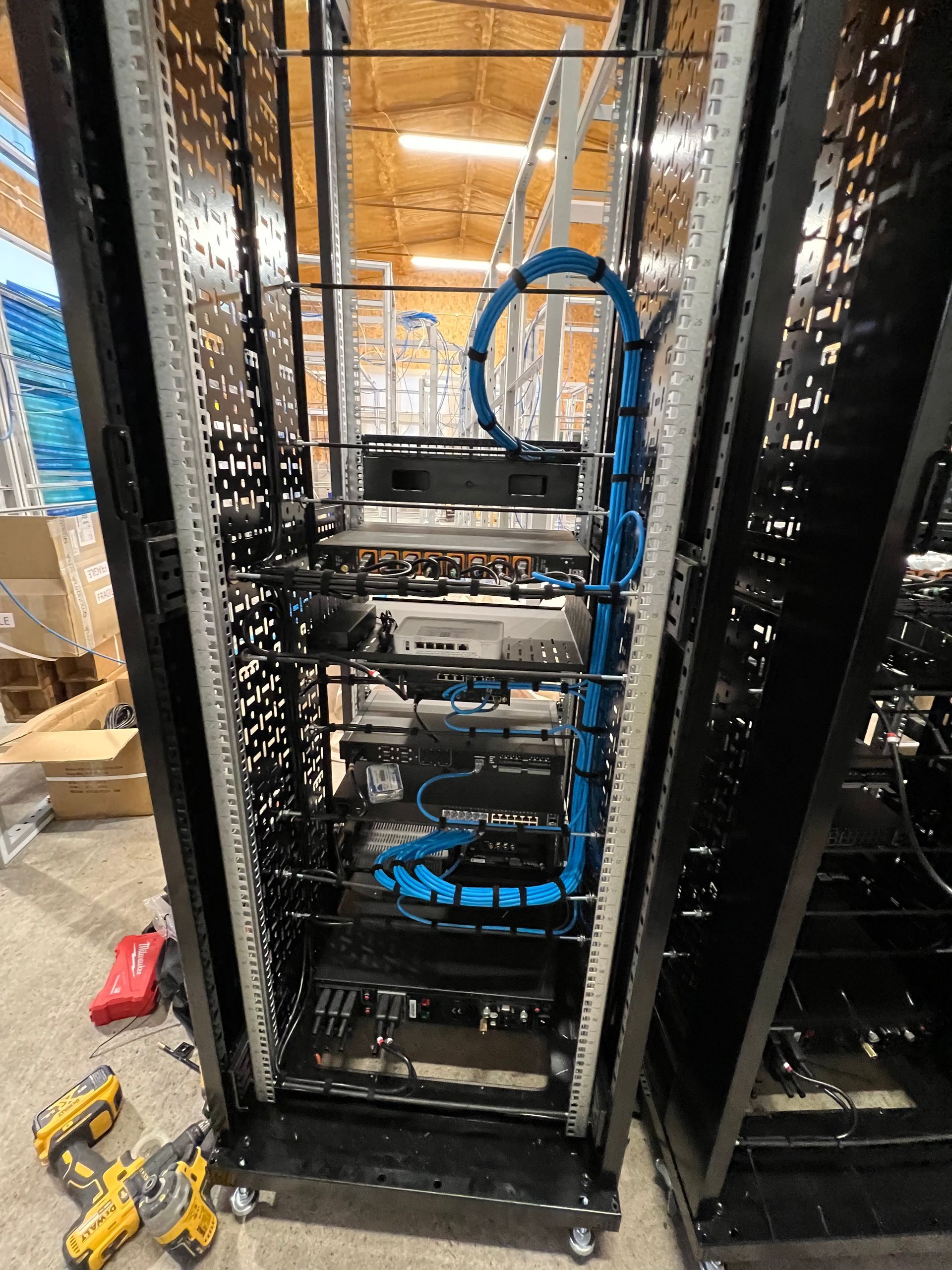
So, our preferred approach is always to build racks away from the client site at one of our facilities. Due to us utilising exhibition display system panels we had practically eliminated any onsite construction work being required. We still employed an approach of building all the server racks offsite at our workshop.
This also meant that we could optimise our installation efforts by creating a form of manufacturing assembly line process at our workshop e.g. rack building 6 identical racks, commissioning and configuring on the bench 6 of each type of equipment.
We adhere to industry best practice with regards to rack design and building including many of the Rack Building for Audiovisual Systems AVIXA Standard (F502.01:2018).
We also create the project within Control4 Composer and carried out the initial configuration of the systems. We also download and then update the relevant firmware and software patches to the latest releases for all equipment.
The equipment was then removed from the racks ready for transportation to site.

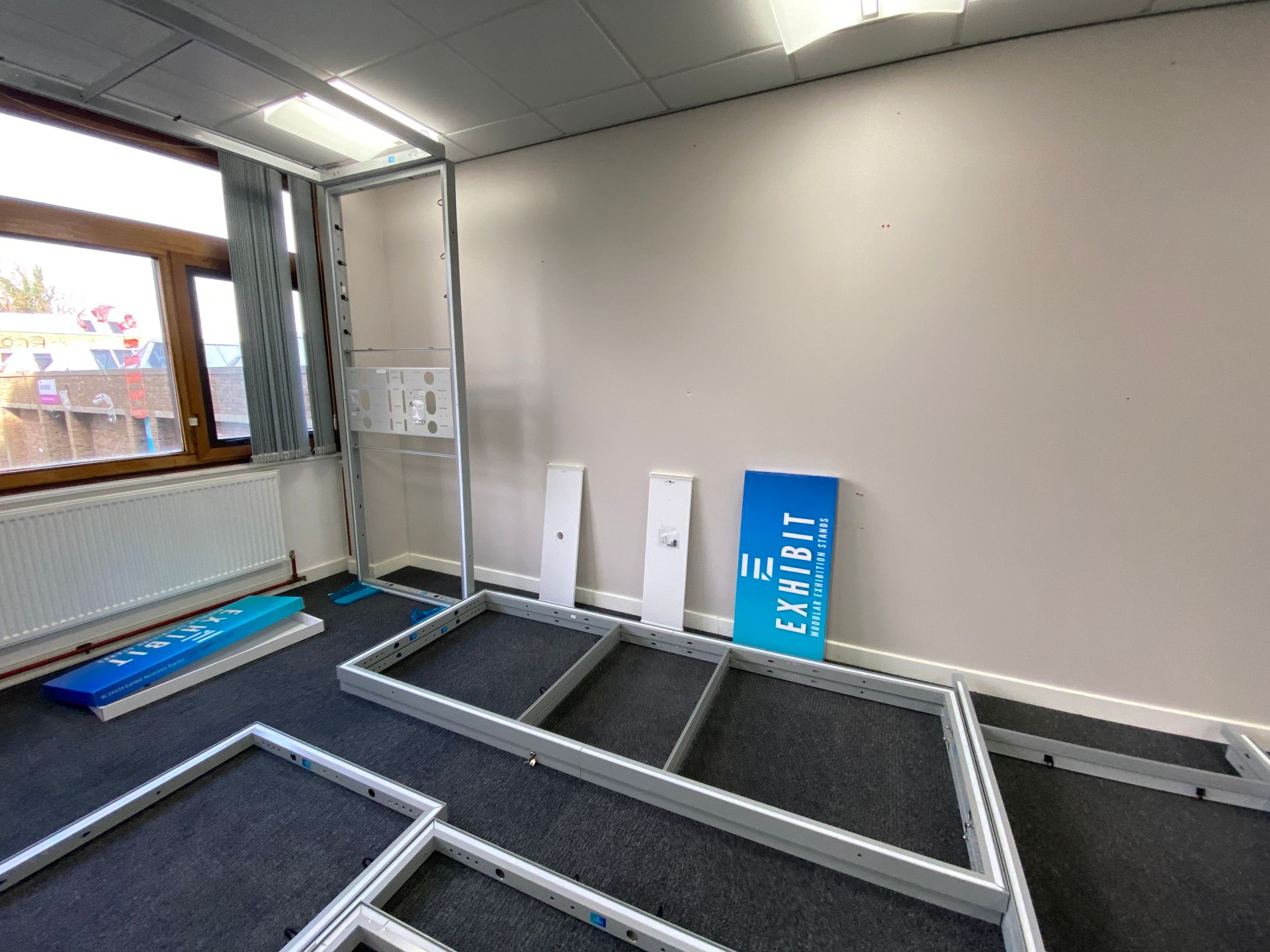
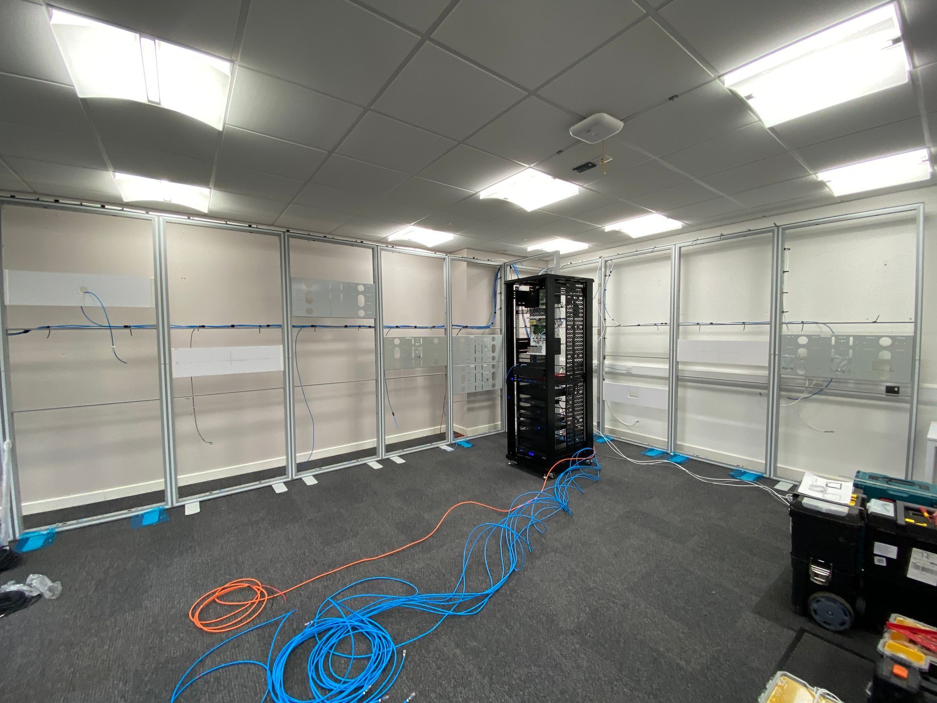
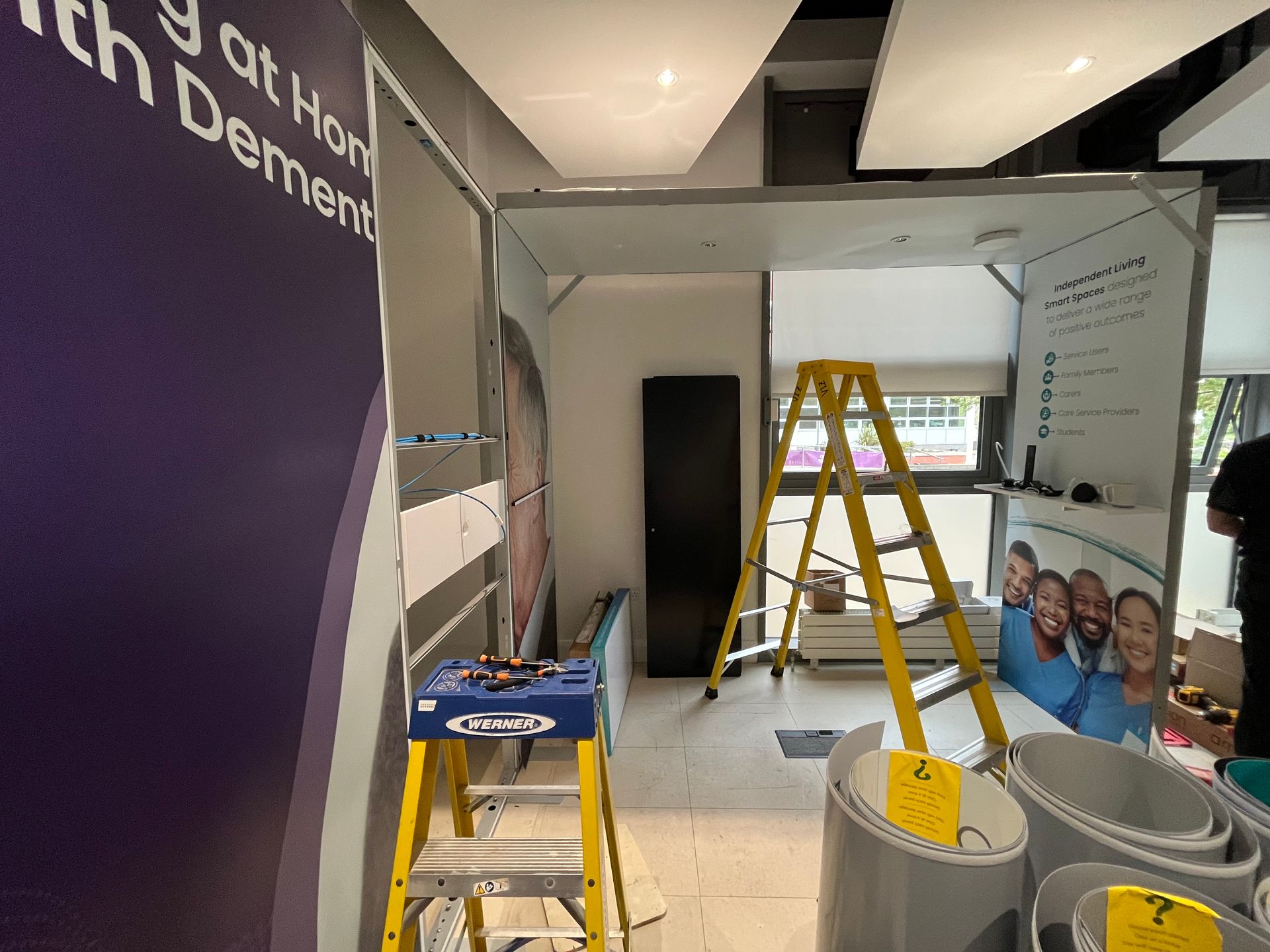
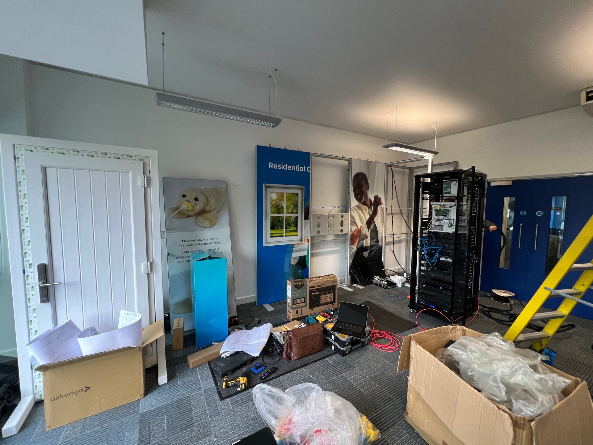
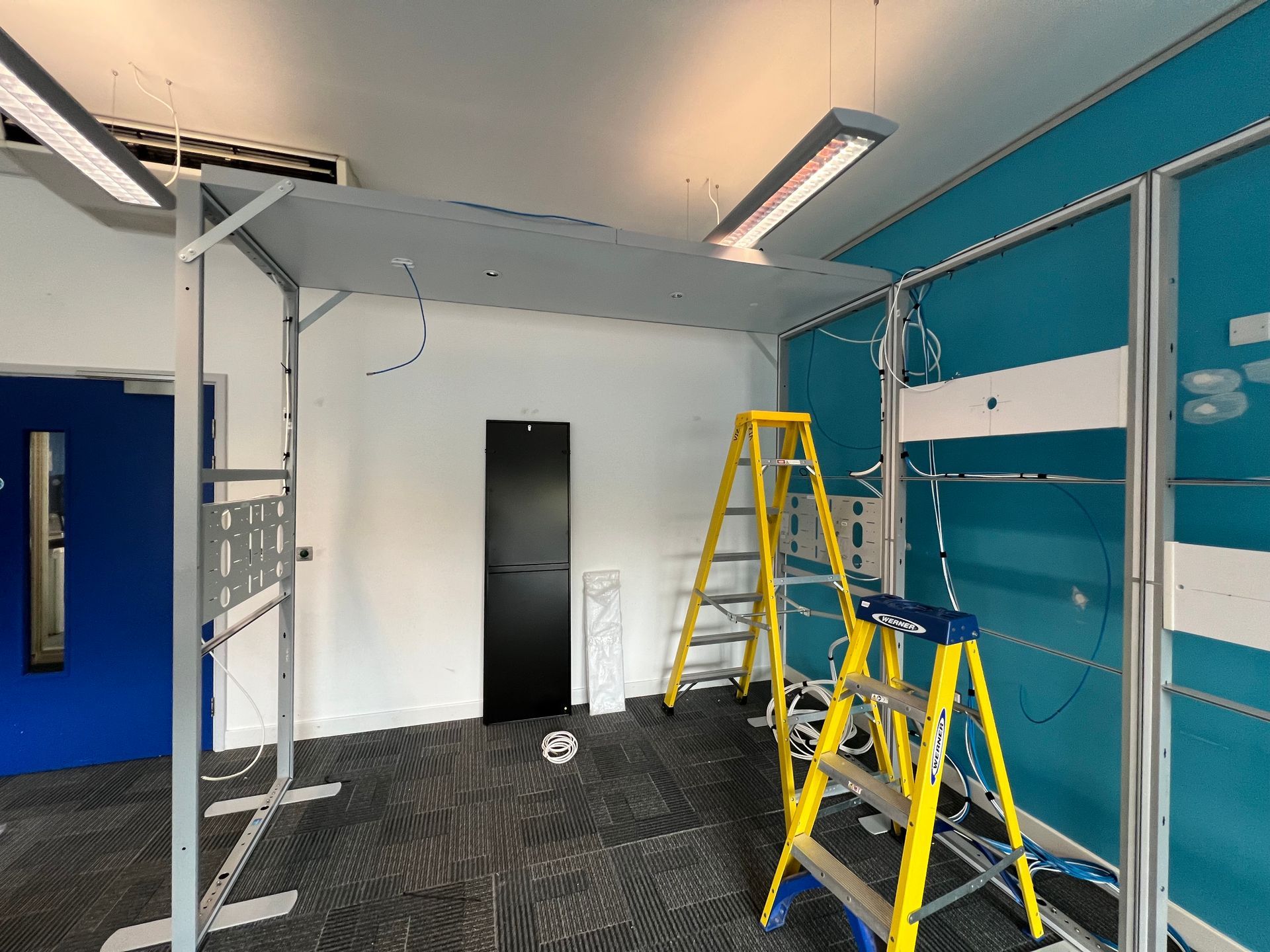
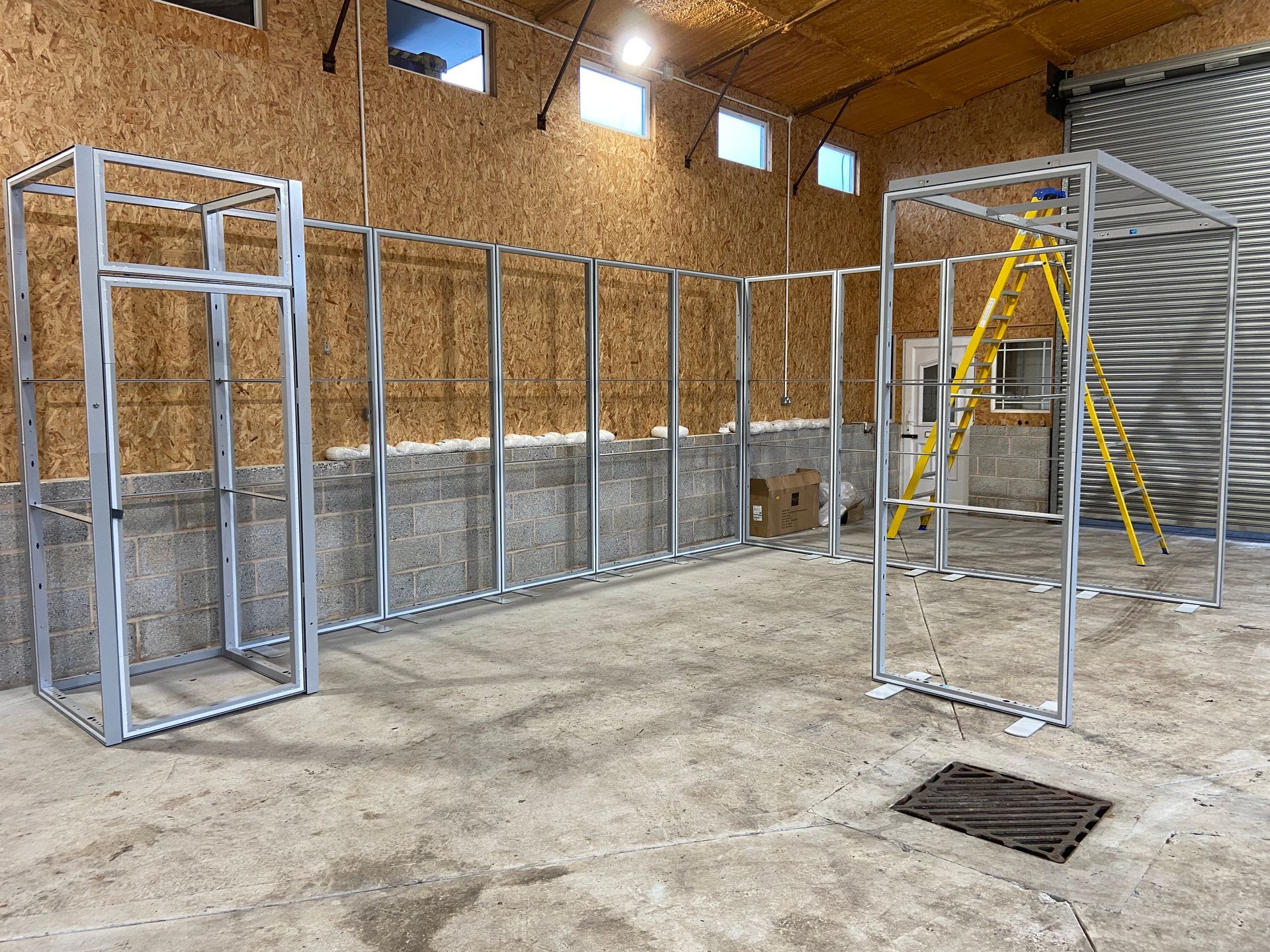
3rd fix phase
During the 3rd fix phase, we carried out the following activities at each of the 6 colleges:
- Equipment delivered to site several days in advance of the installation team
- Exhibition space display system panel reassembly
- Loading the racks with the relevant equipment
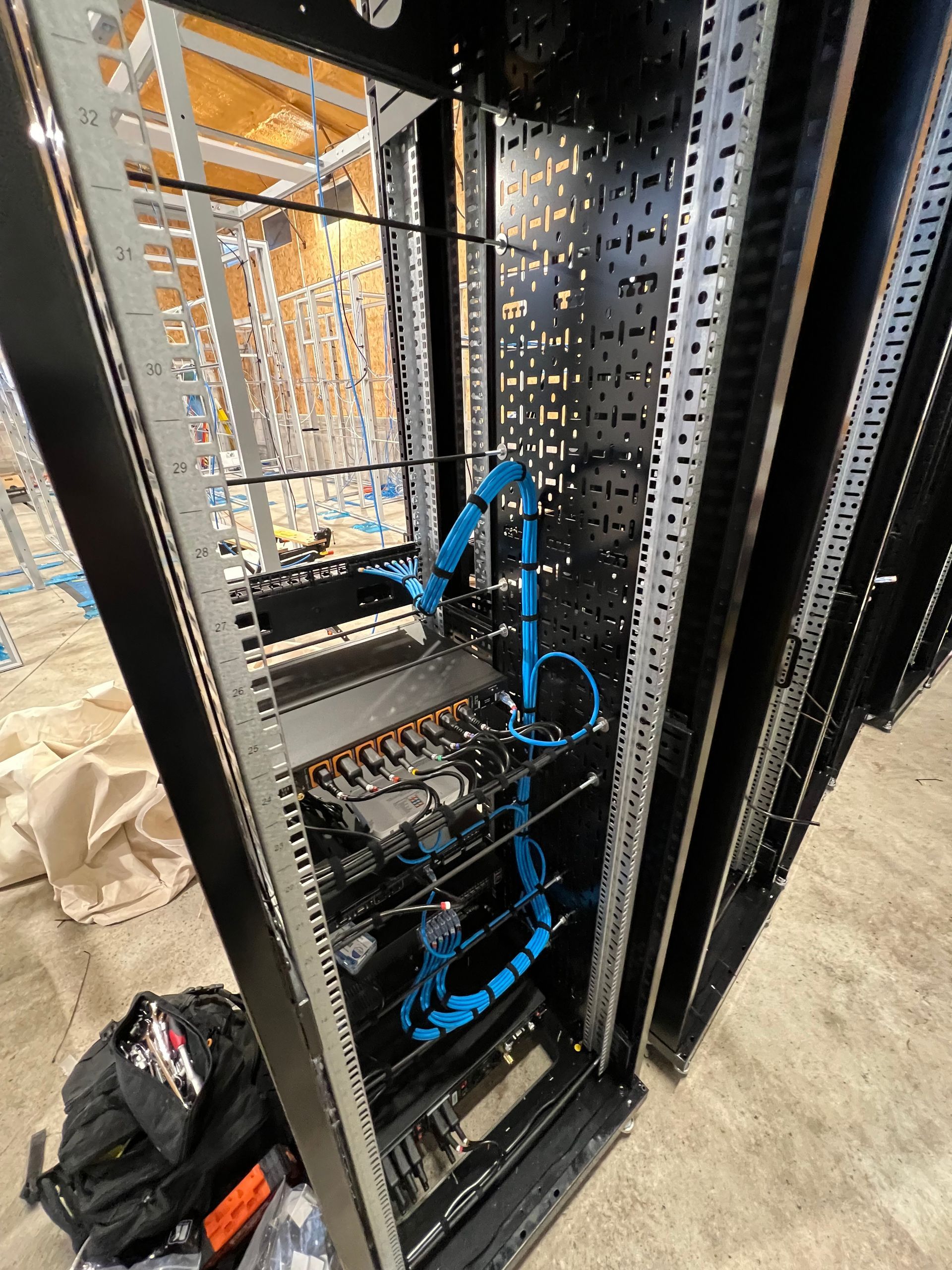
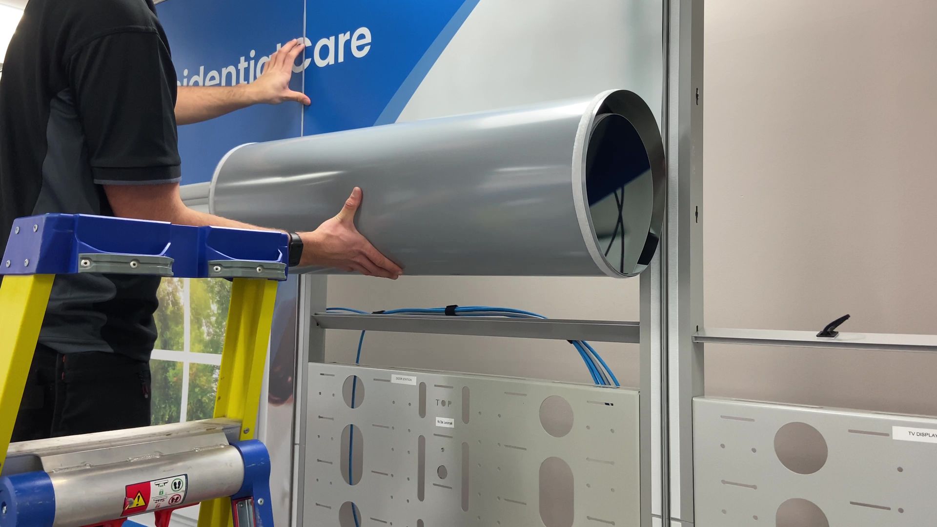
- Installing the power and non-power cables looms
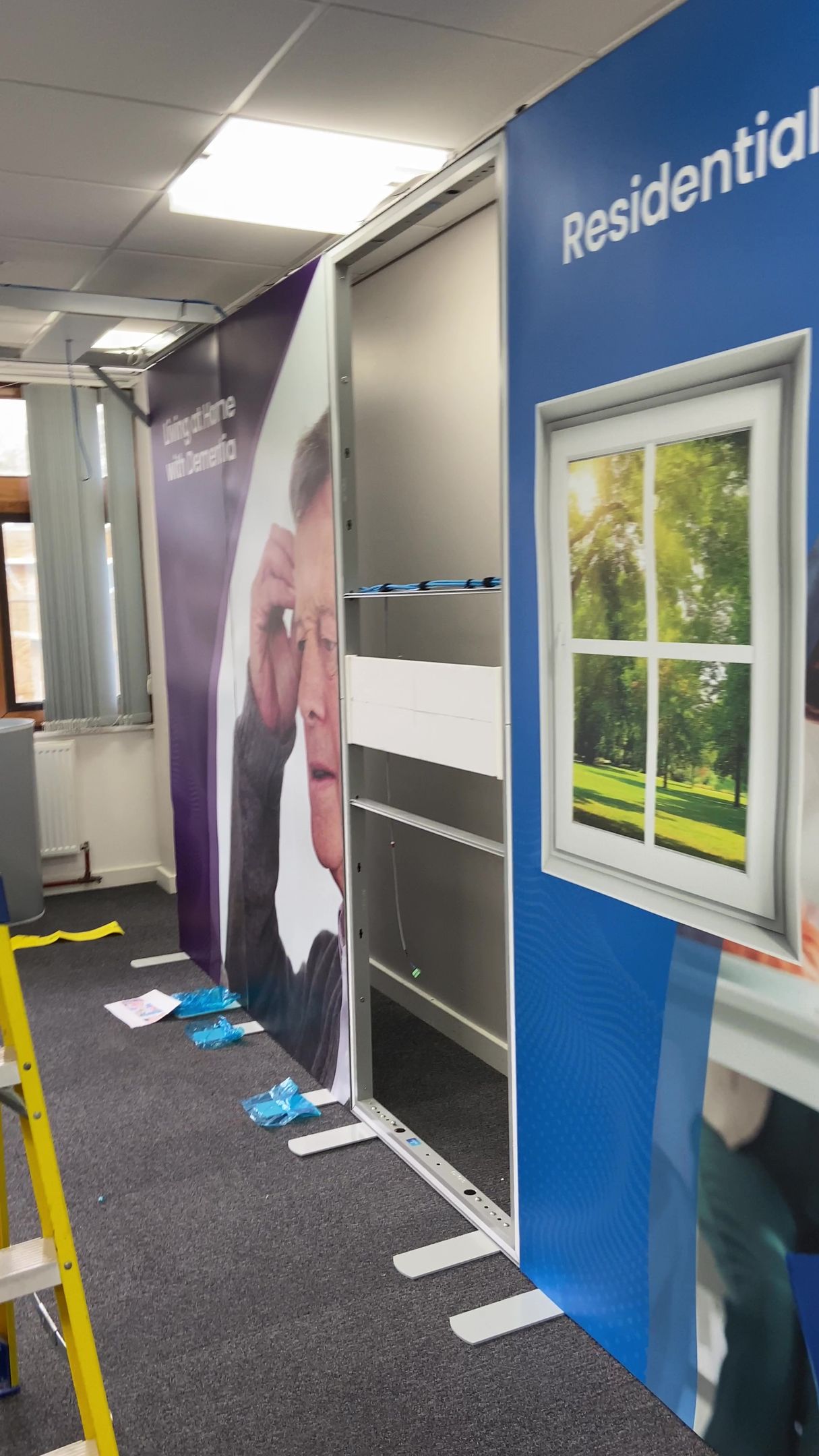
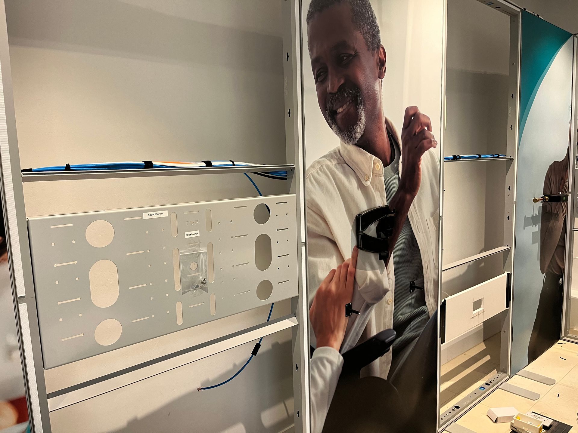
- Attaching the vinyl printed graphics onto the exhibition space display system panels
- Mounting the various equipment displayed on the panels
- Fully testing equipment
Following the installation onsite, we also delivered in person training sessions for the teachers at all 6 college locations. This training included a presentation about the idea behind the concept of an Independent Living Smart Space, a brief explanation of the history of smart home technologies, an overview of the 3 different scenarios and suggested steps for providing a comprehensive demonstration of the outcomes.
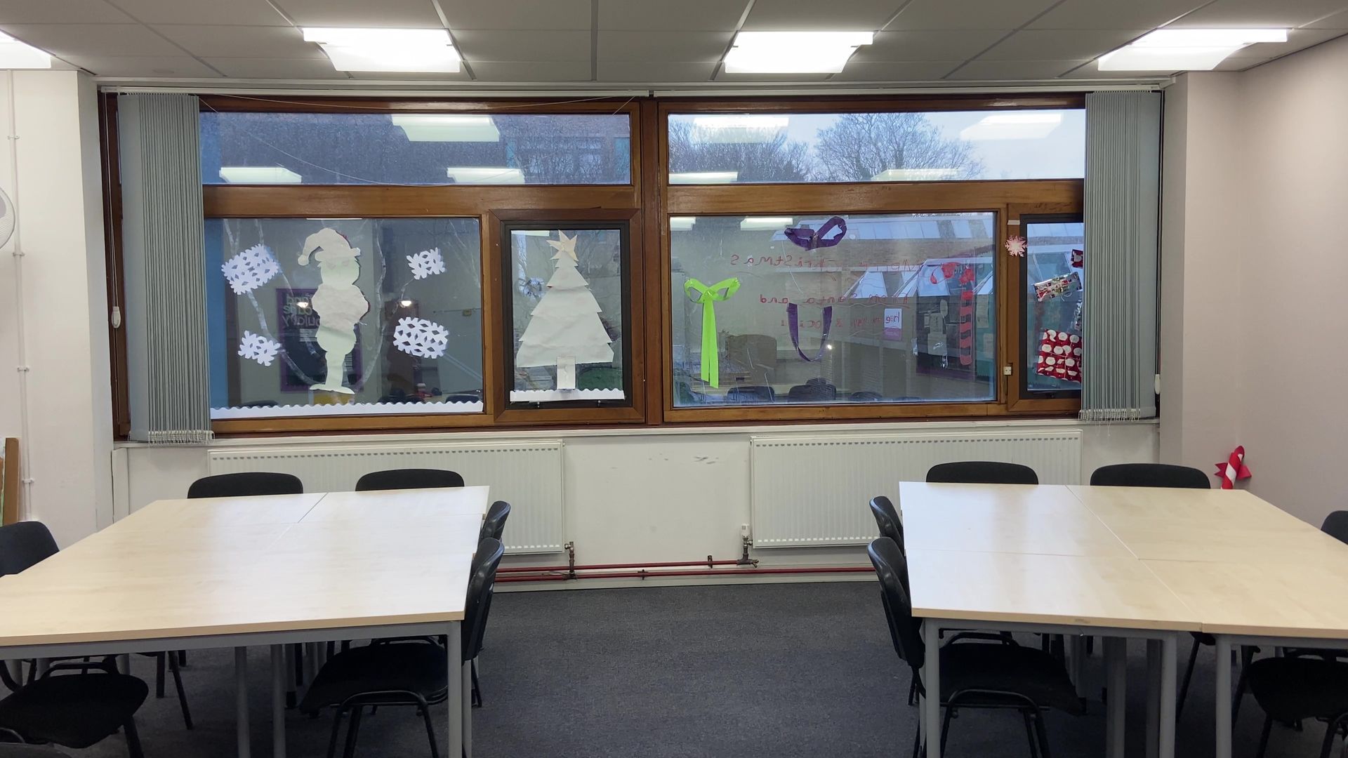
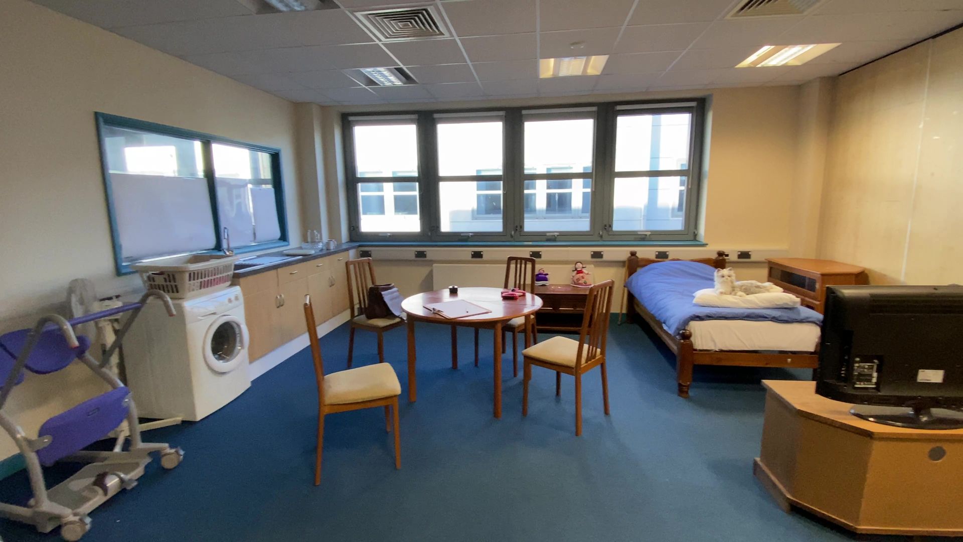
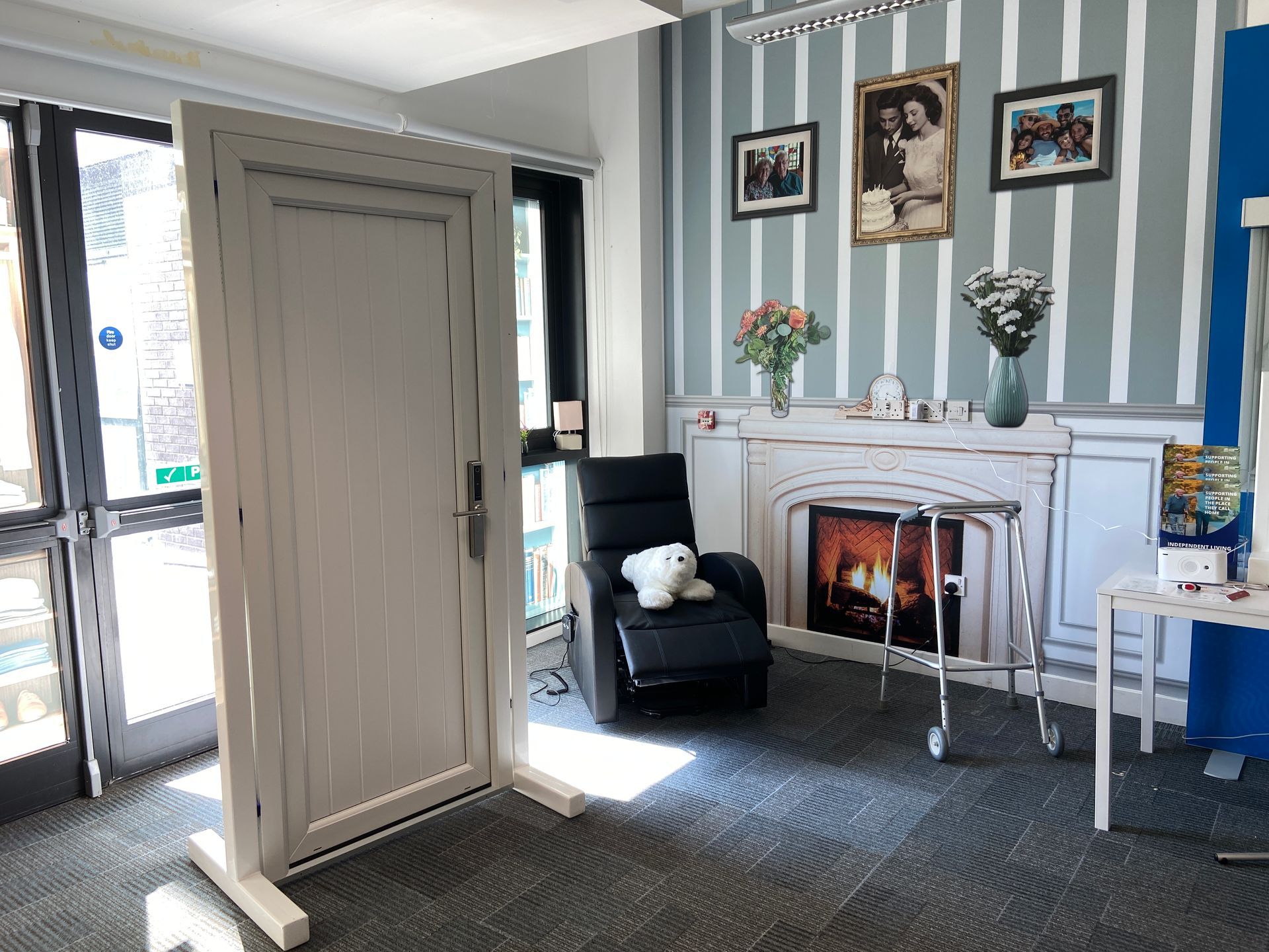
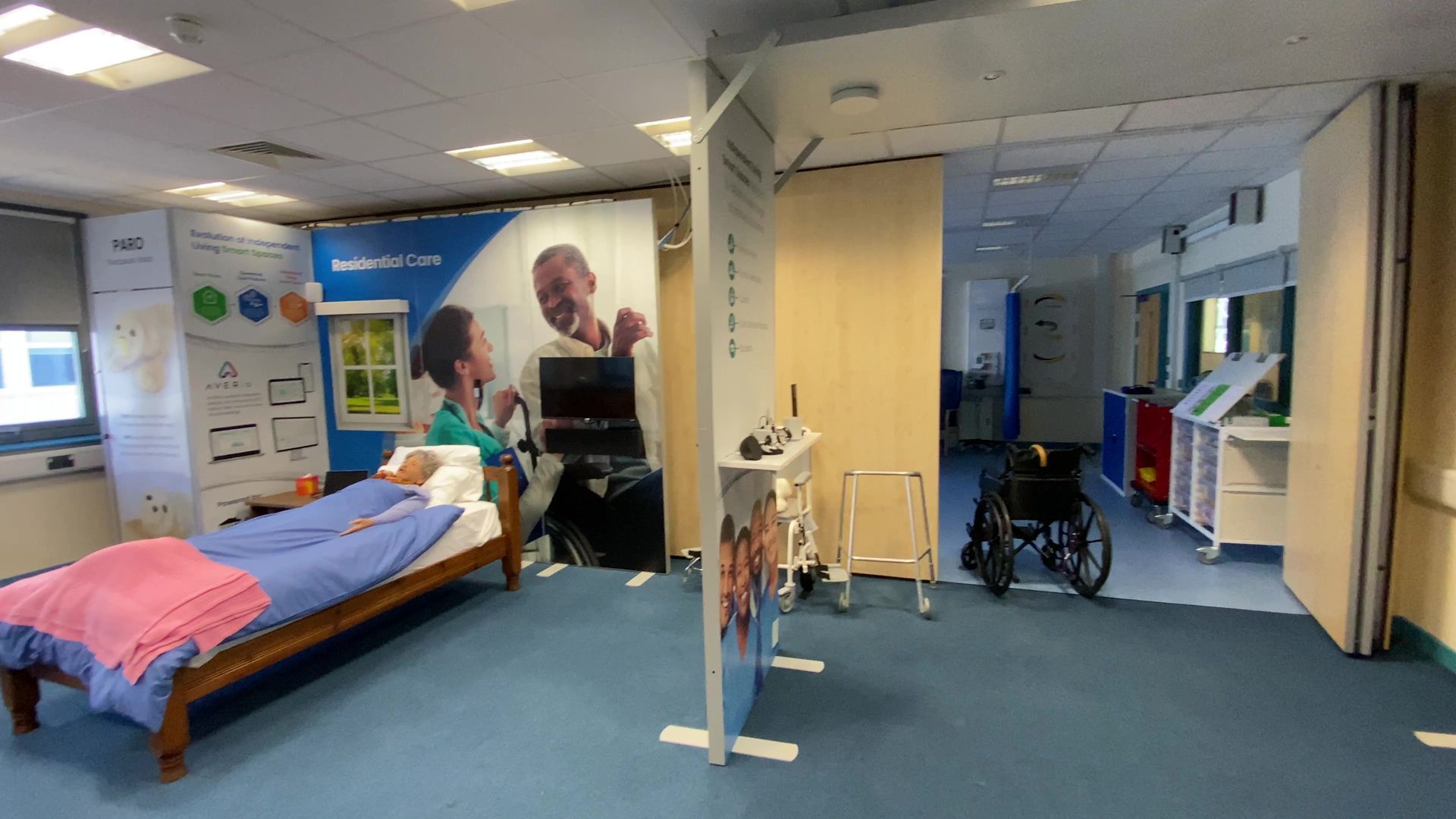
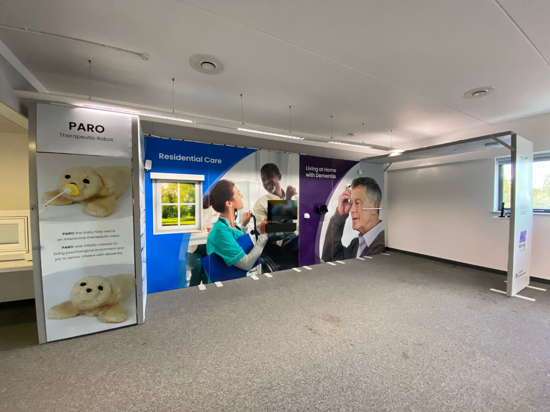
Finished demonstration suites
After we completed our installation, the client furnished their demonstrations suites to make them feel even more immersive…we think the spaces are an amazing environment for students and external stakeholders to learn about the art of the possible in relation to the evolution of assistive technologies and our concept of Independent Living Smart Spaces.
If you would like a similar installation, fill out the contact form below for a
Free of Charge & No Obligation Initial Consultation.

Installed equipment
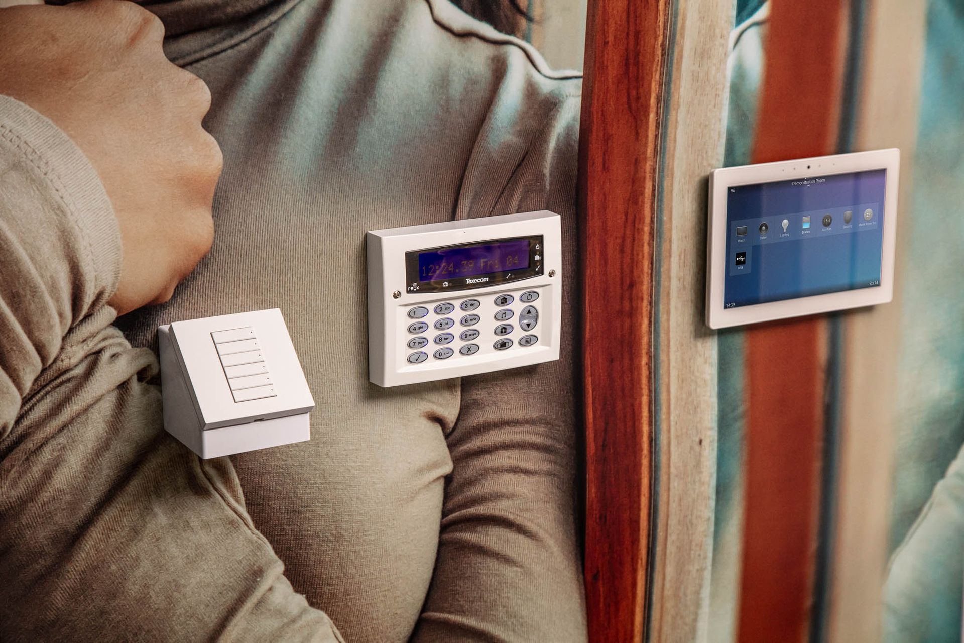
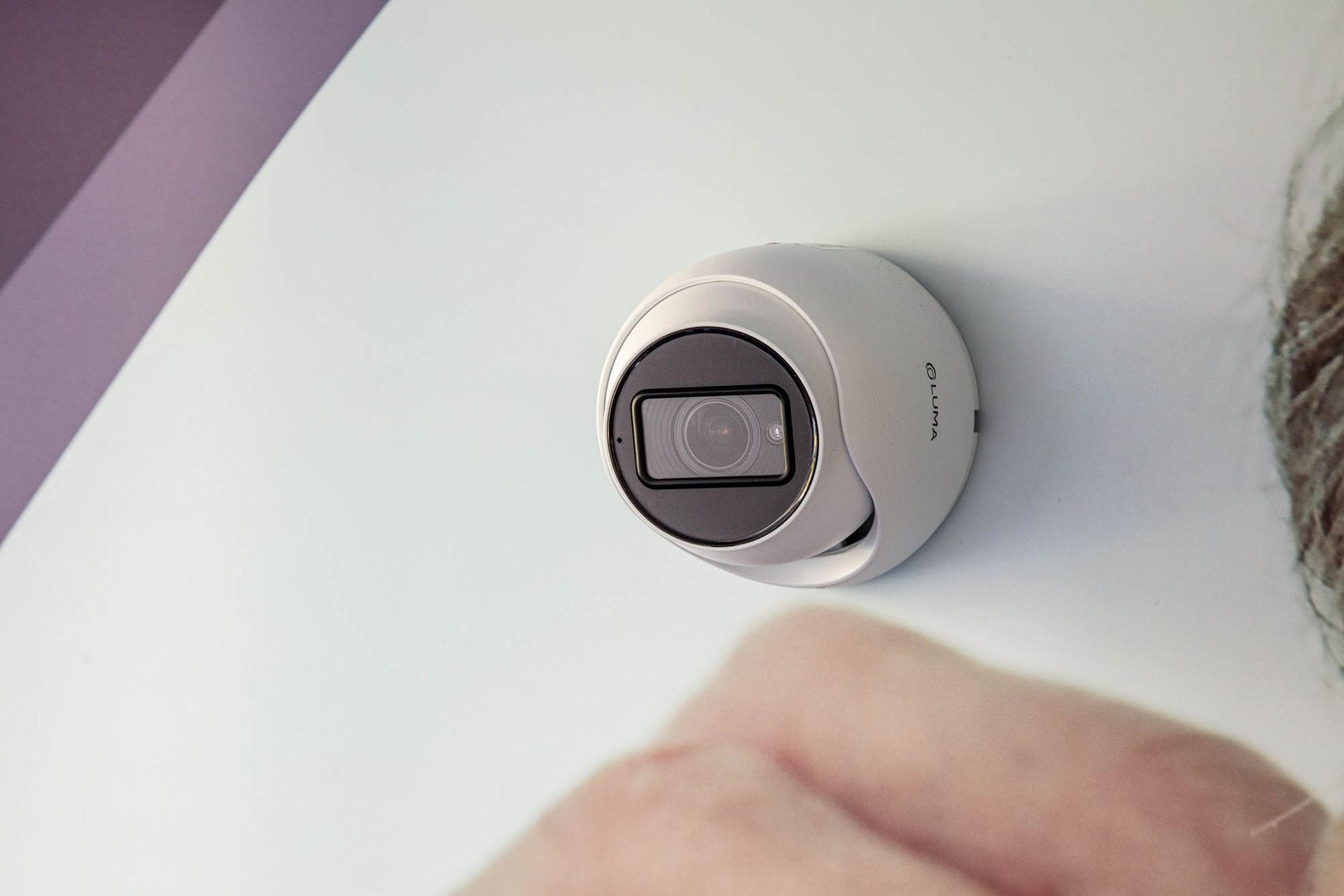
Safety & Security
- CCTV camera (Control4 Luma CCTV Camera utilising line crossing functionality to trigger Control4 programming)
- Intruder Alarm Panel (Texecom), Keypad, PIR & Communication Module (connected to the Control4 controller via software driver)
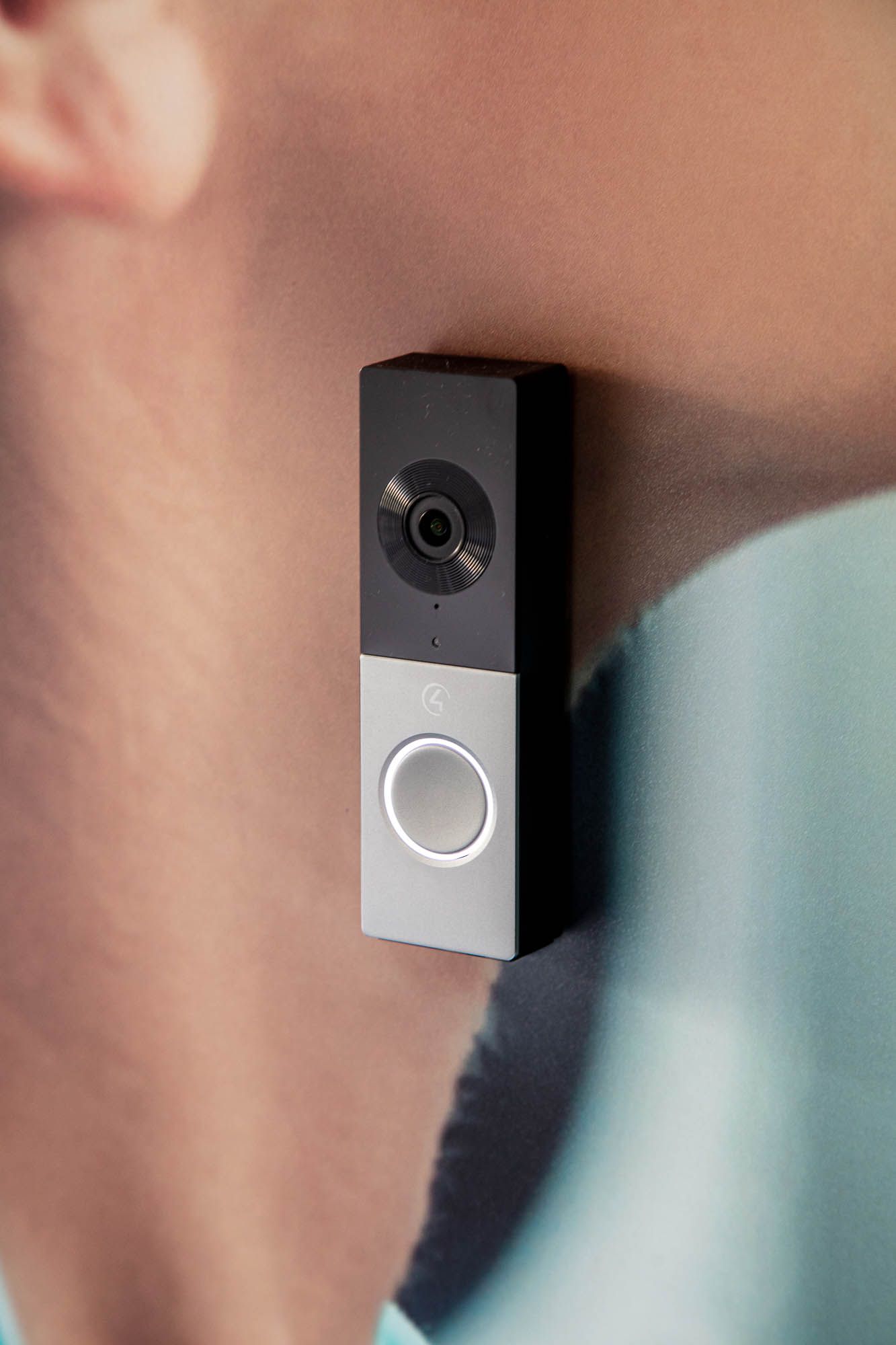
- Doorbell (Internet Connected) – Control4 Chime Doorbell
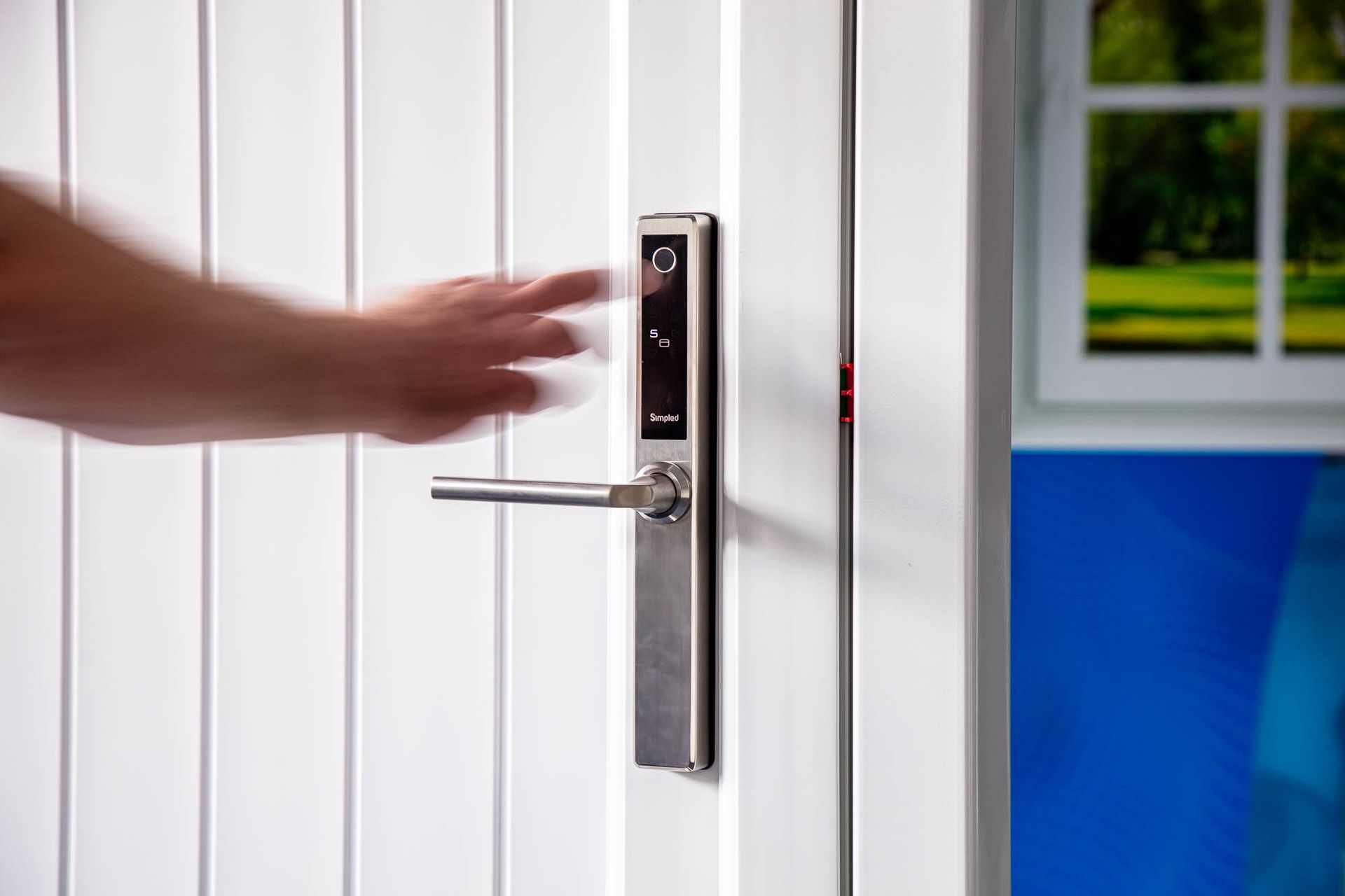
- Smart Door Lock(s) including Biometrics (supplied installed onto a real full-sized external door within a steel supporting frame, the door itself has a multi-point door locking system, the smart door lock was fully integrated with Control4 via driver)
- Door/Window Sensors (Fibaro Door/Window Sensor)
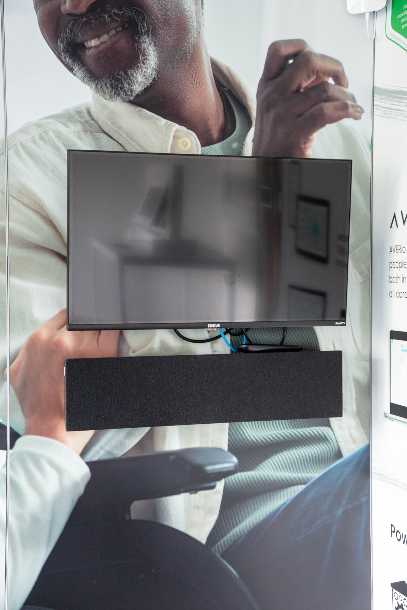
Home Entertainment
- Multi-Room Video – Roku TV Display 32" & TV Mount
- Multi-Room Audio – Soundbar Speaker (Triad custom width to match TV) & Amplifier (Control4 Triad 1 amplifier)
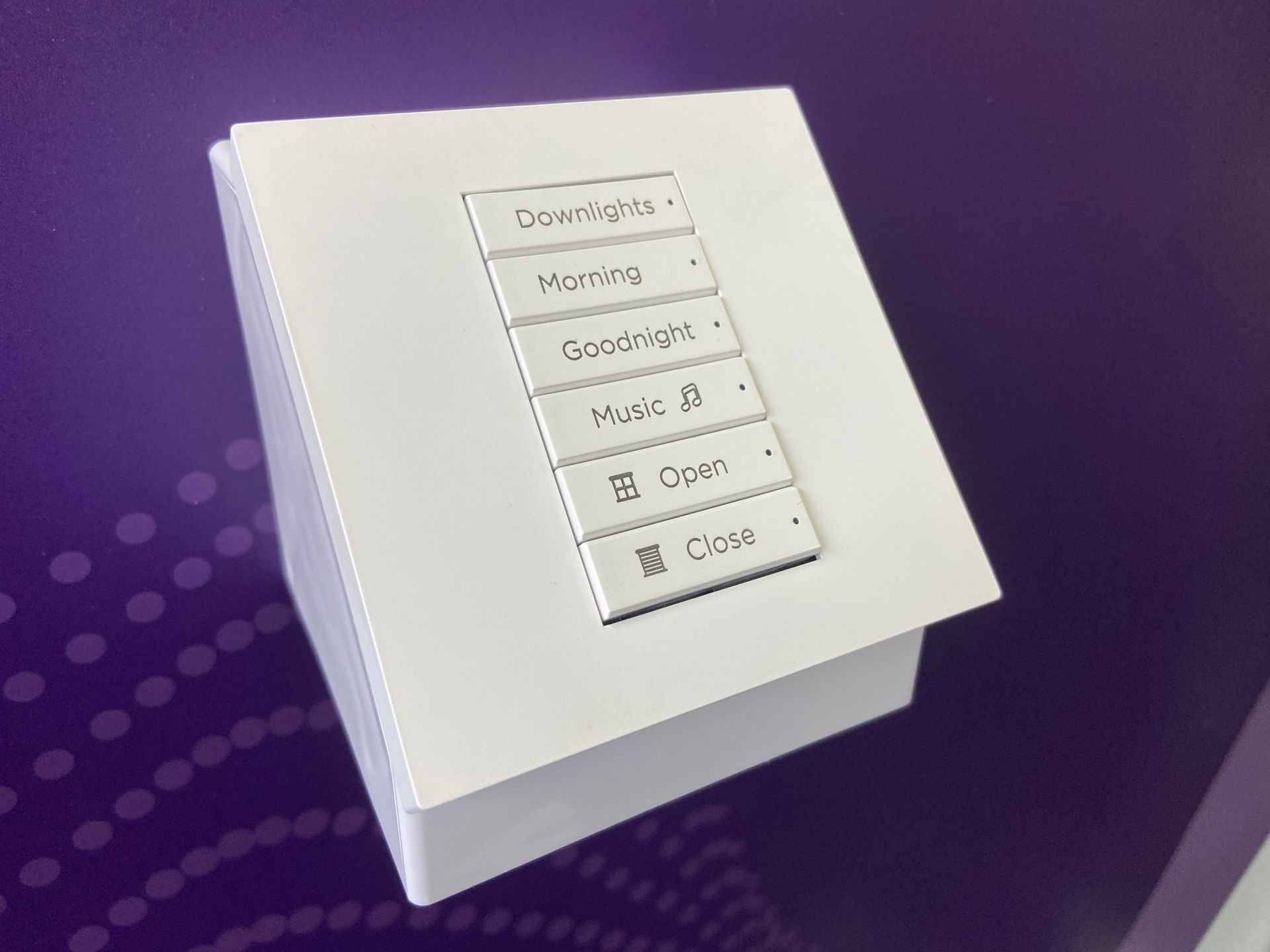
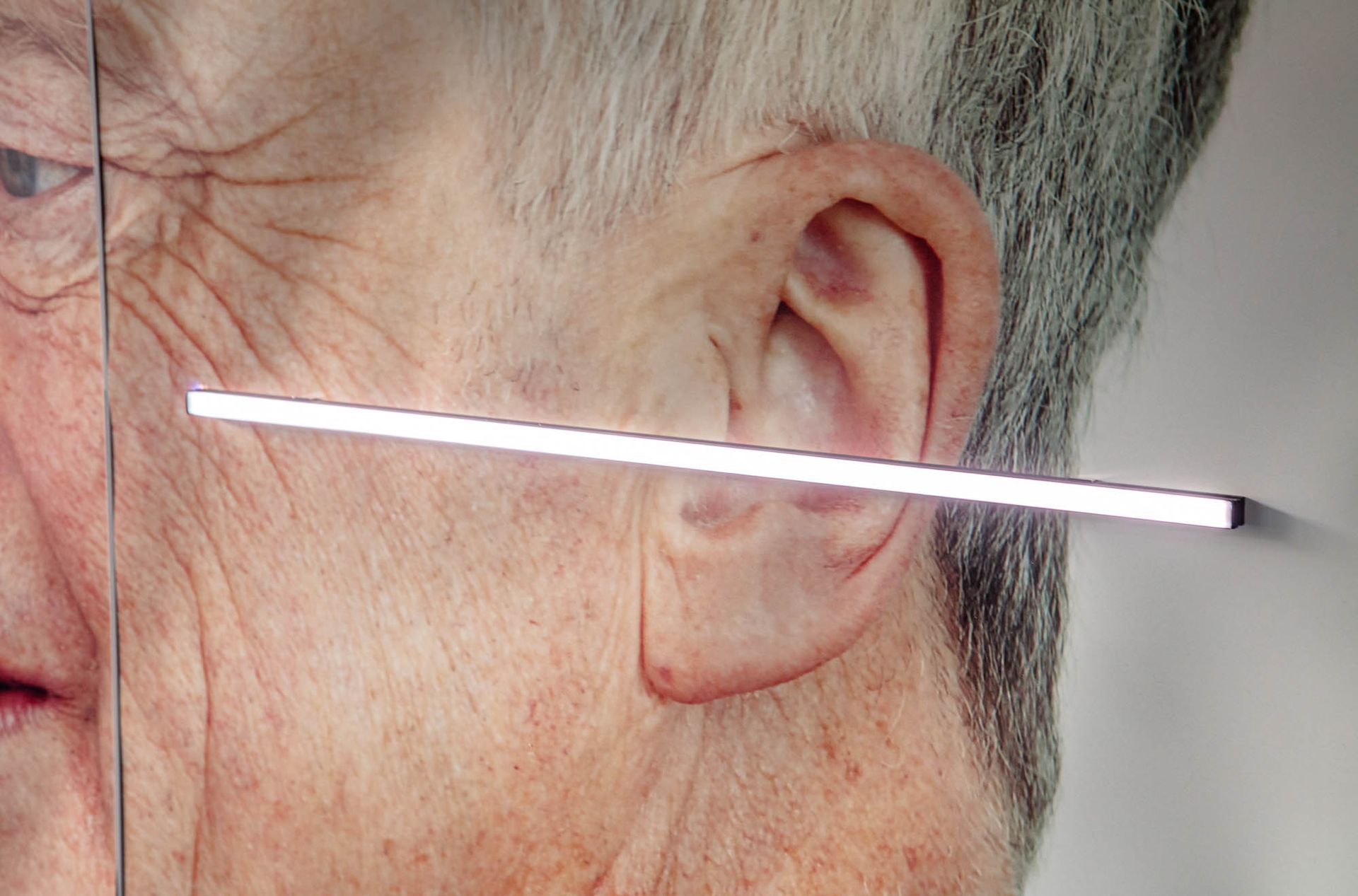
Smart Lighting
- Multi-Room Lighting – Control4 Wireless Light Switches (1 x Dual Load Dimmer Switch & 1 x Keypad Switch – both with custom engraved buttons)
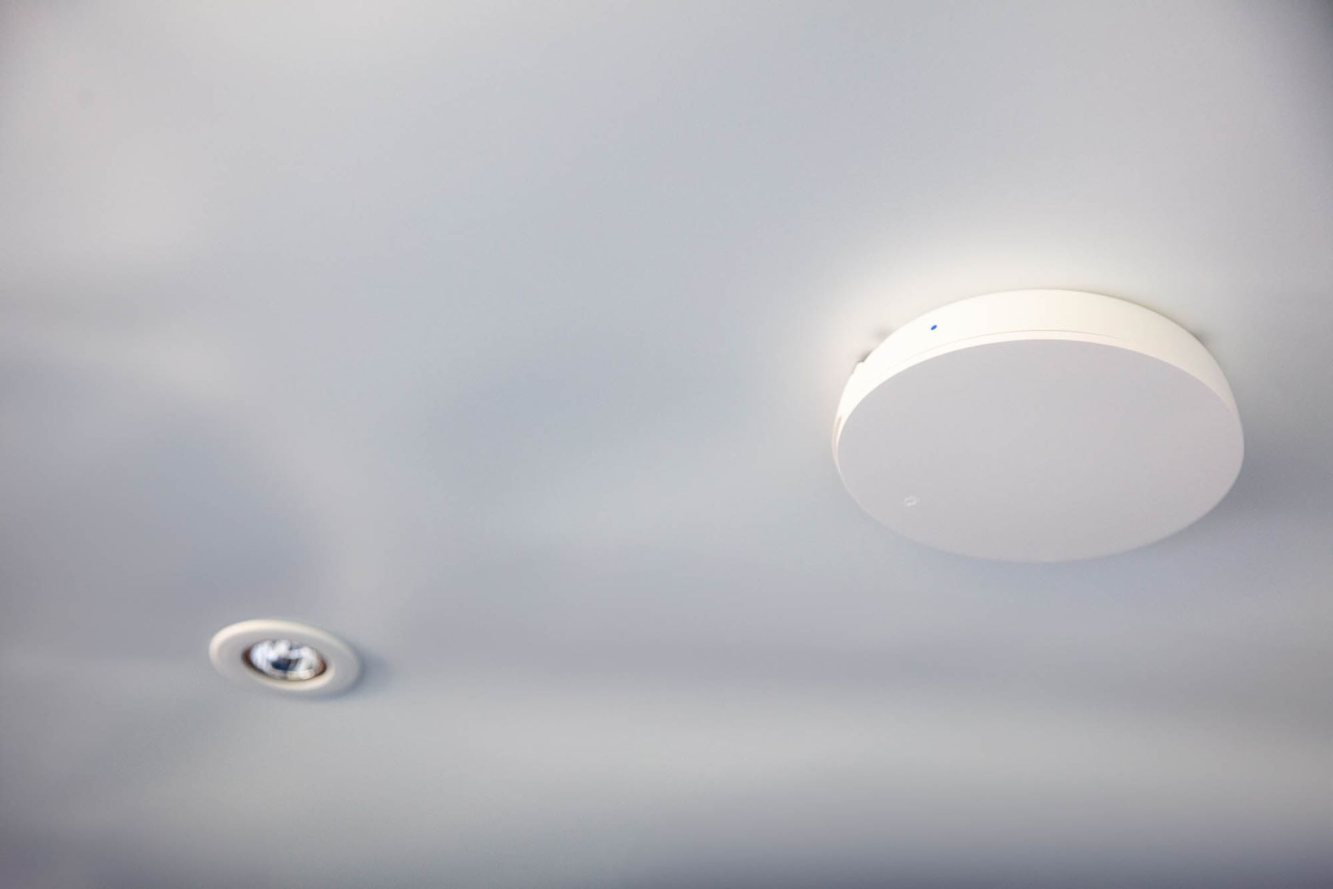
- Light Fixtures - Colour Change Tunable Light (Control4 Vibrant Zigbee Dimming Module and Colour Tunable LED strip light in a custom length LED profile with diffuser cover)
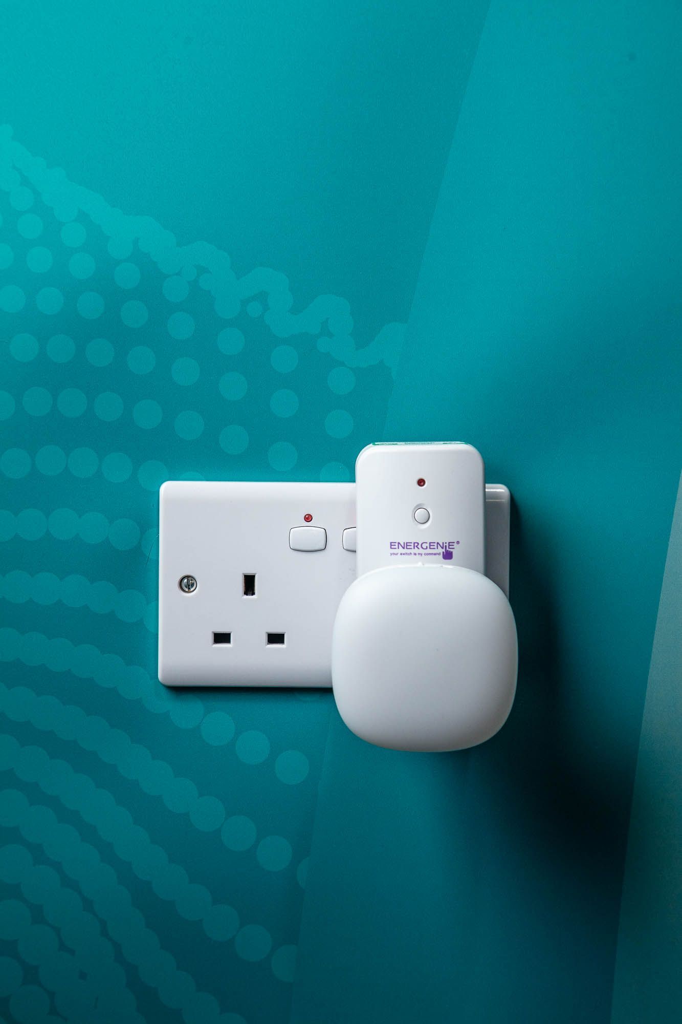
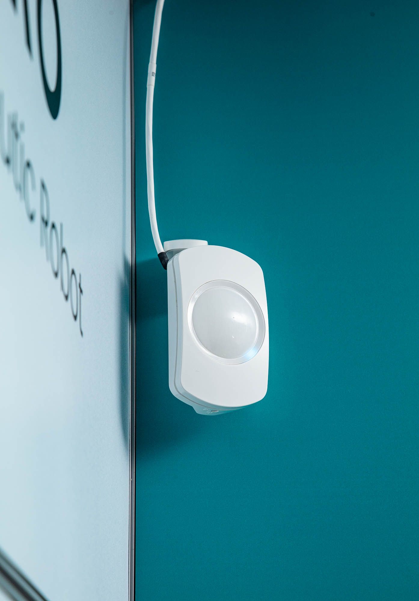
Comfort & Convenience
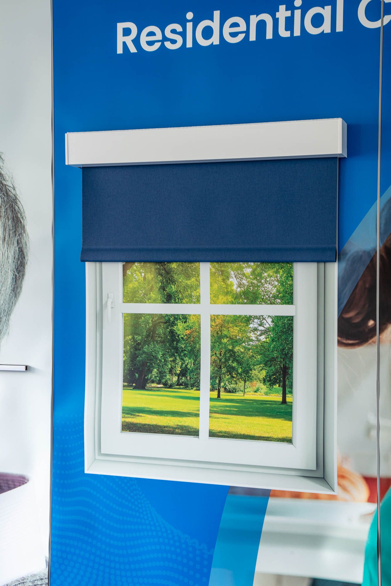
- Shades/Curtains - Automated Blind (QMotion wired roller blind with communication module)
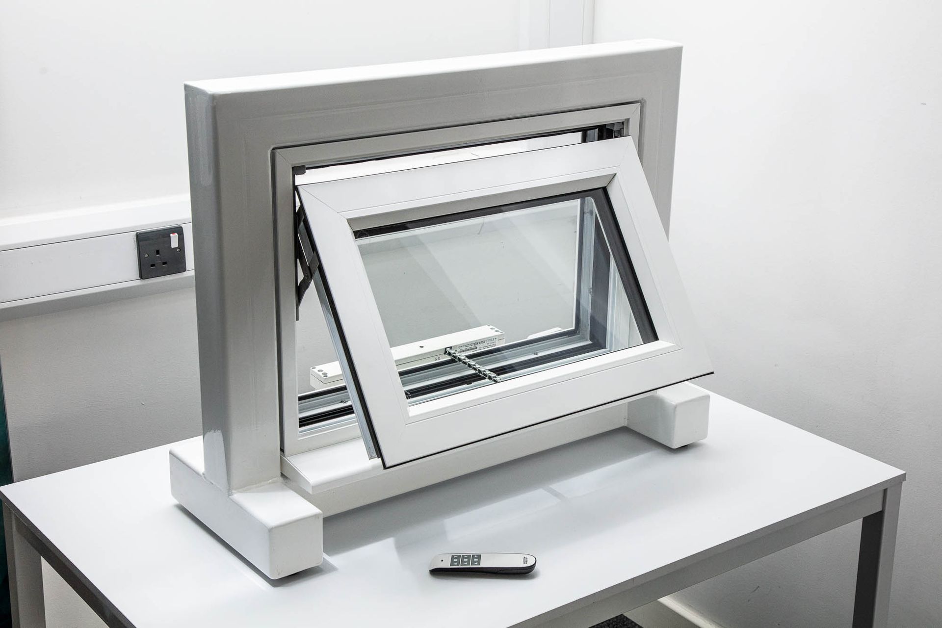
- Motorised Window Actuator (Window Master control panel and window actuator attached to real full-sized external window within a steel supporting frame)
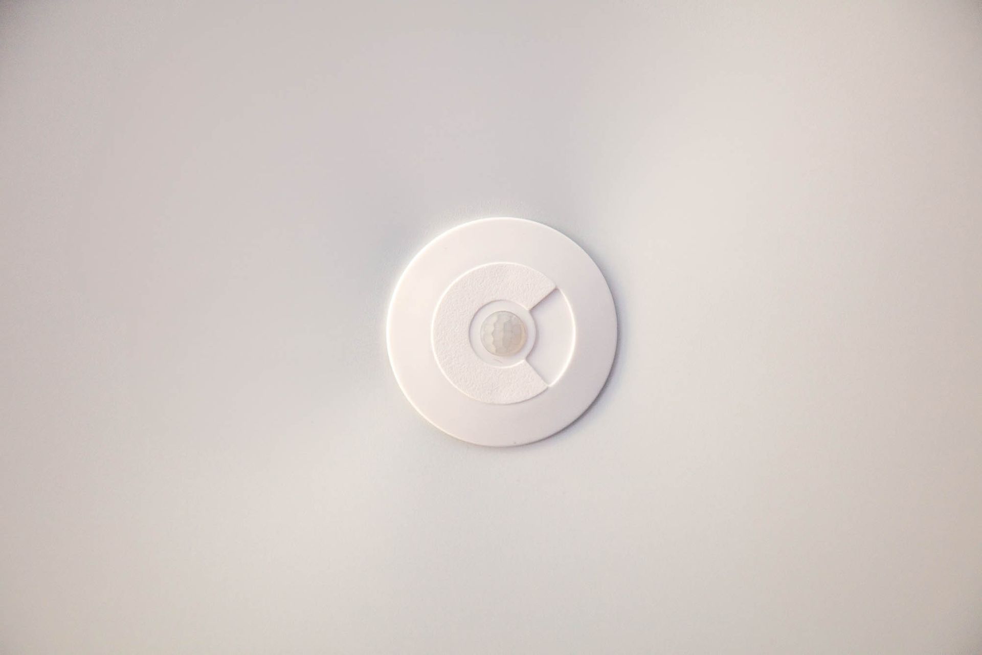
- Motion Sensor (Faradite - Contact Sensor)
- Energenie Hub and Smart Mains Power Socket
Smart Home Control System
- Smart Home Automation System (Control4 Core 3 Controller)
- Input/Output Extender (Control4 IO Ext – integrated with Motion Sensor, QMotion communication module & UPS)
- Control4 Drivers (Standard):
- Texecom
- Energenie
- Roku TV & associated Mini Drivers e.g., Netflix, YouTube, etc.
- QMotion
- Control4 Drivers (Custom):
- Independent Living Smart Spaces Driver (Automated Spaces Owned Driver)
- Simpled Smart Lock (Uses the TT Lock cloud platform) driver – we worked closely with Janus Technology to help them create this new driver specifically for this project
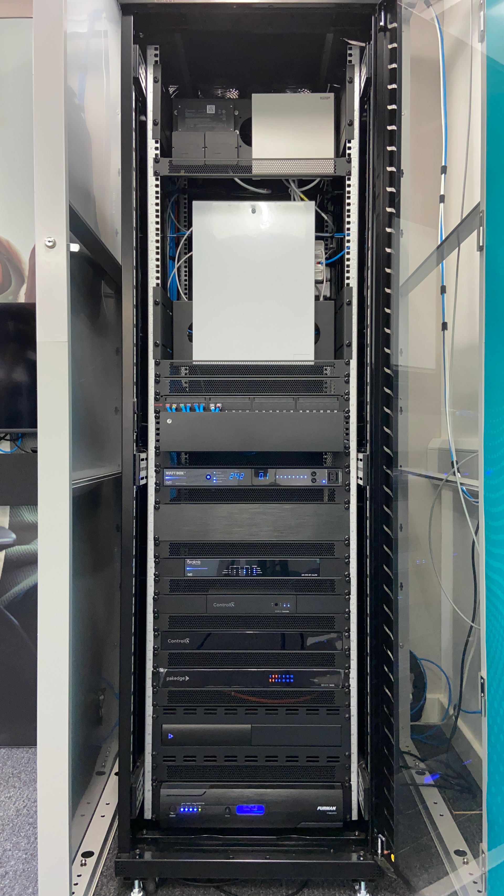
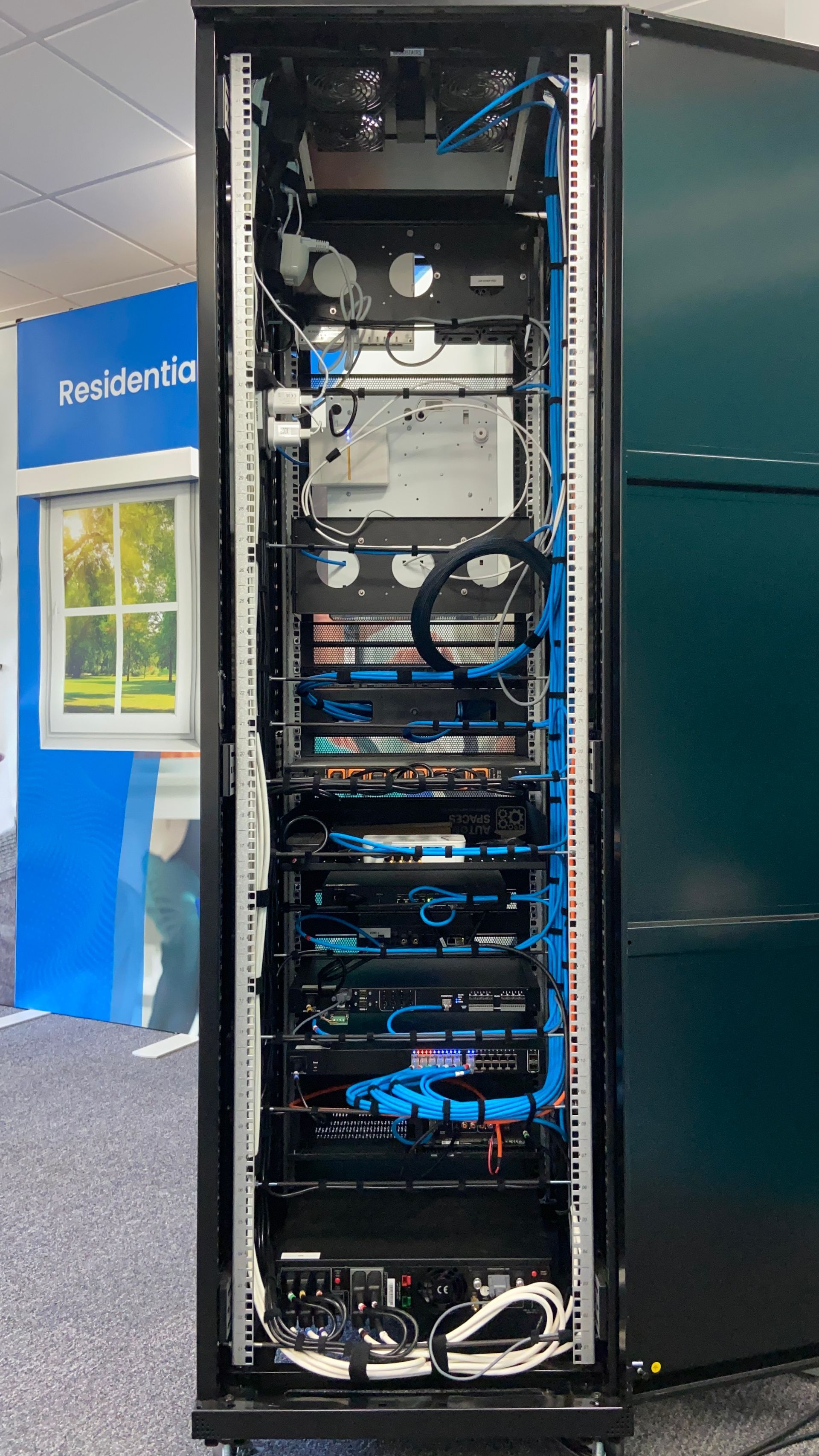
Intelligent Networking
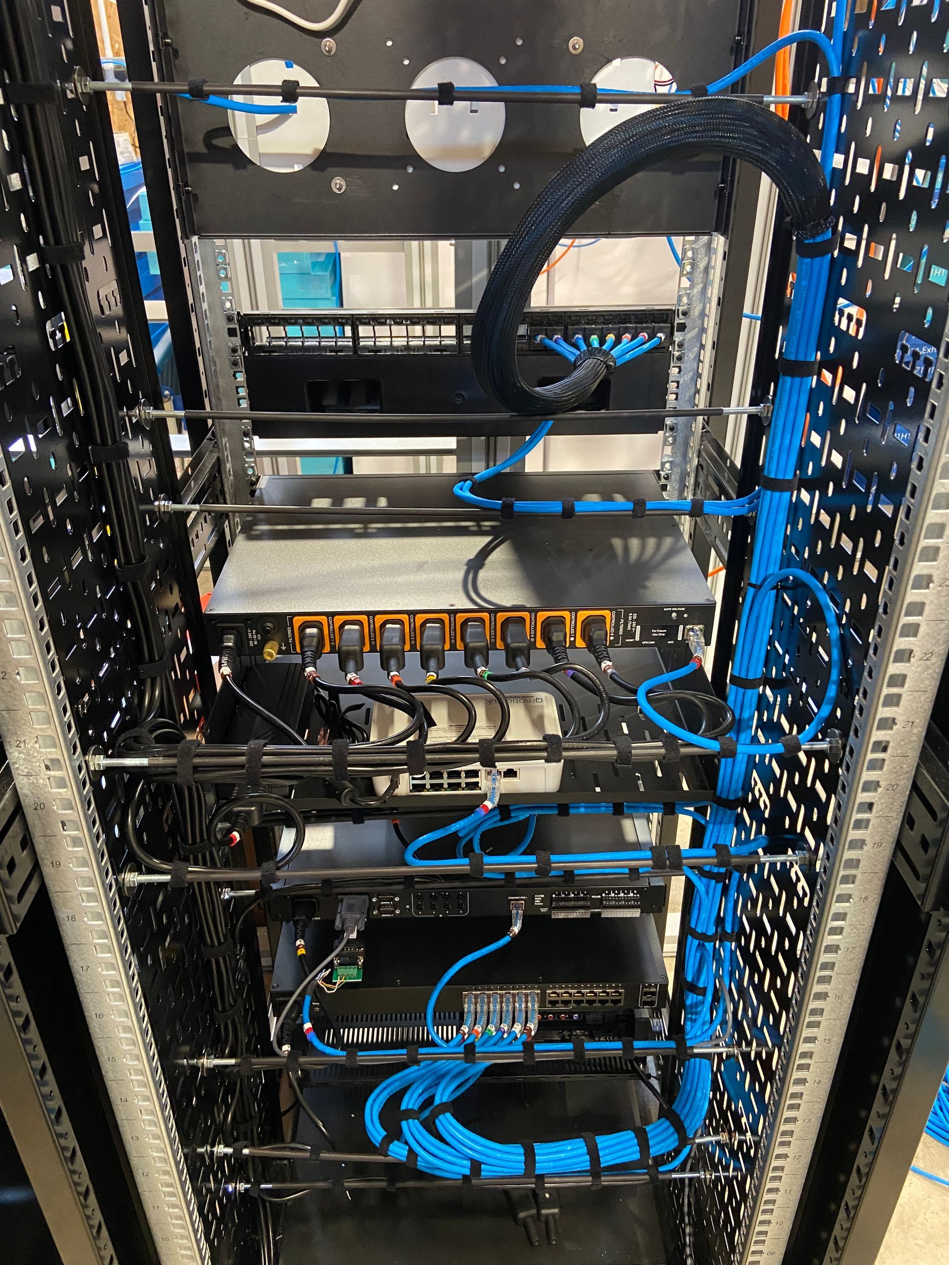
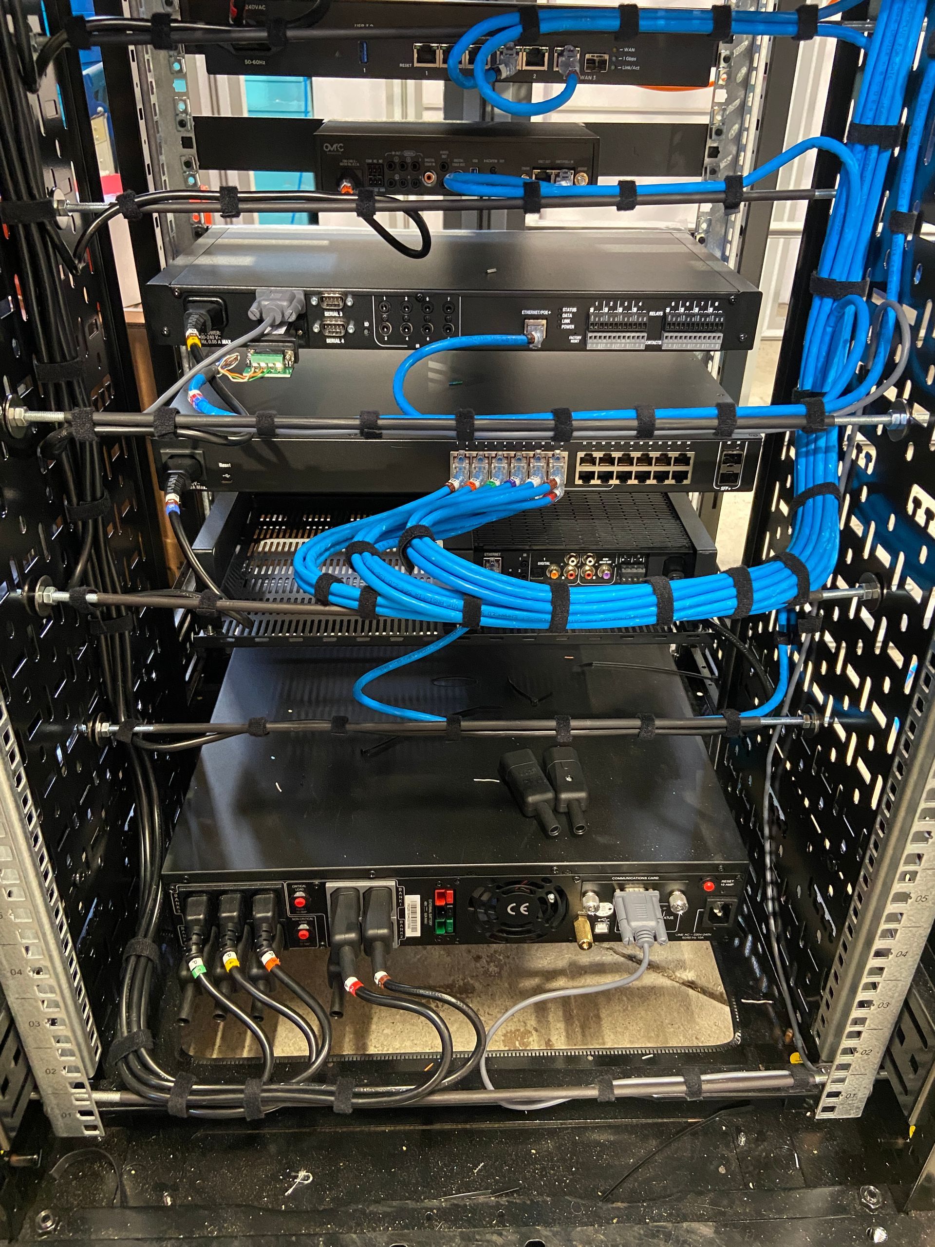
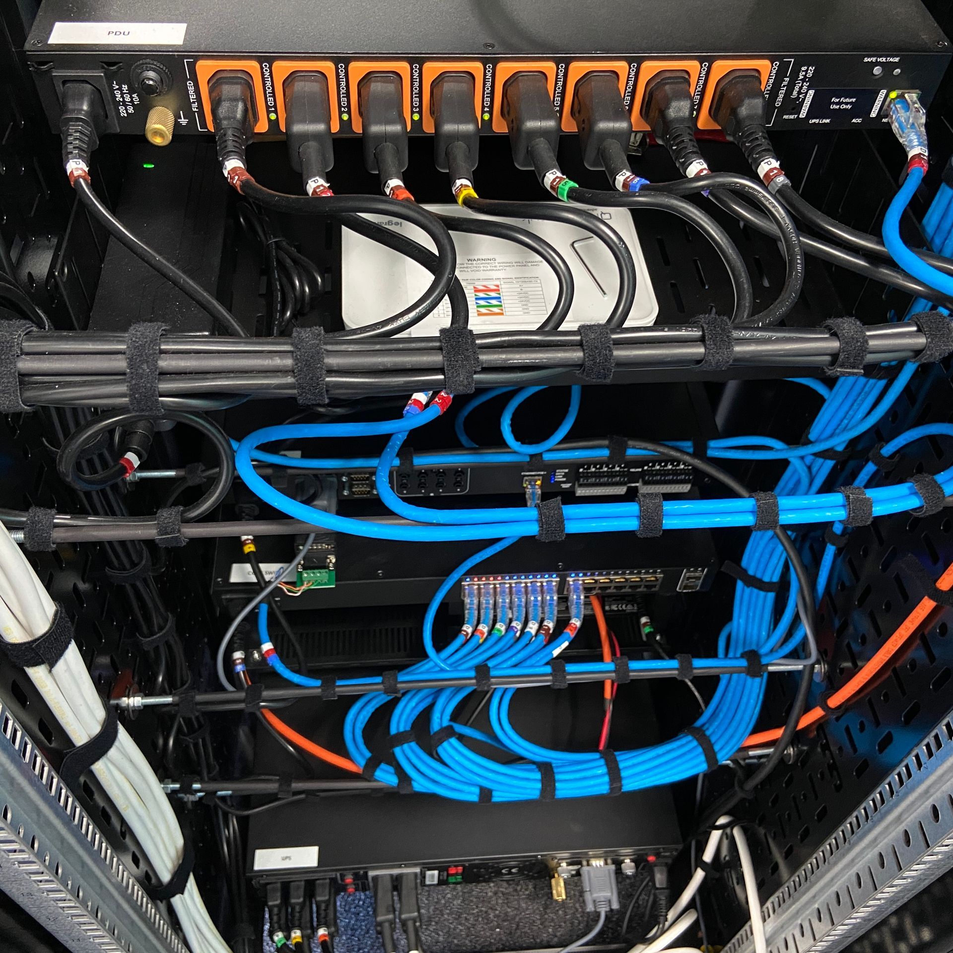
- Uninterrupted Power Supply (Furman UPS with approx. 90 mins runtime)
- Power Distribution Units (Control4 WattBox 8 Outlet PDU)
- Router (Control4® Araknis Networks® 310 Series Dual-WAN Gigabit VPN Router)
- Wireless Access Point - Indoor (Control4 Araknis Networks Wi-Fi 6 WAP)
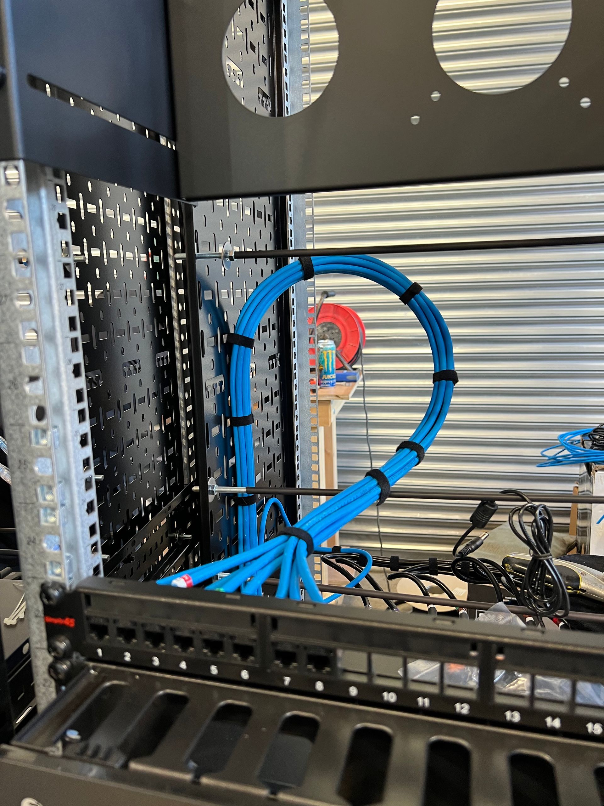
- Wired Home Network - Patch Panel (8 Port Patch Panel housed in rack)
- Network Switch (Control4 Pakedge Layer 3 Managed Switch)
- Server Rack & Accessories:
- 42U Rack & Casters
- Cable Trays (1 for power and 1 for everything else e.g., data, speaker, etc.)
- 19” Rack Shelves
- 19” Faceplates
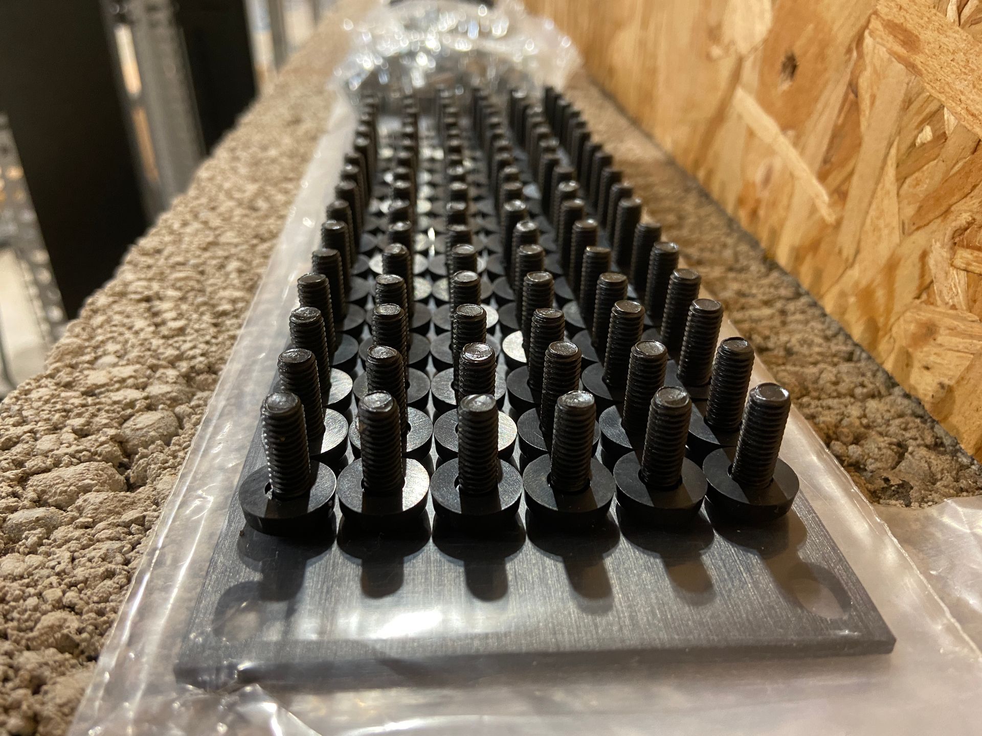
- 19” Universal Mounts
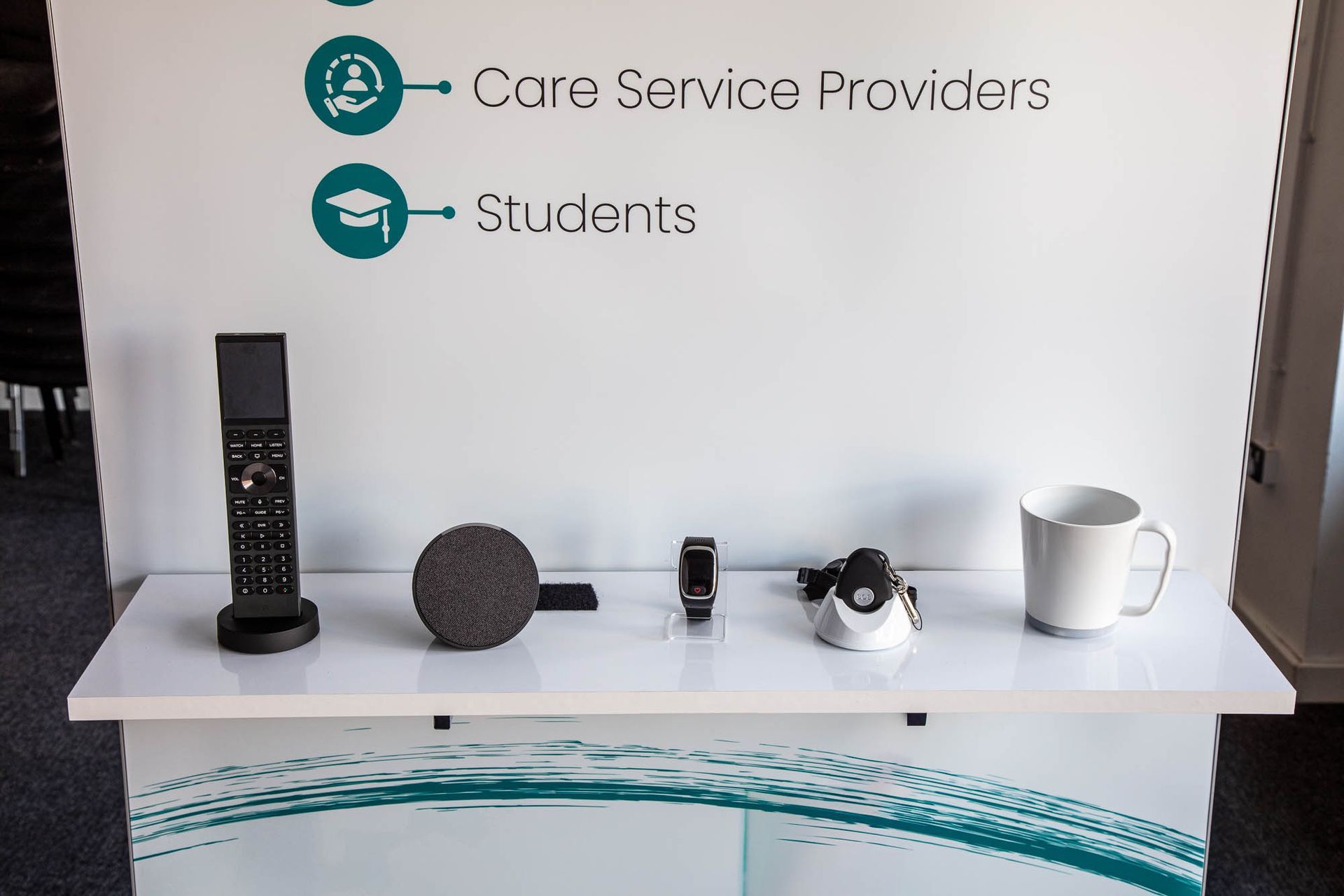
User Experience
- Remote Control (Control4 Halo Remote Control)
- Touch Screens - On Wall (Control4 8” In-Wall Touch Screen)
Independent Living Technology
- Fall Sensor (mmWave radar sensor)
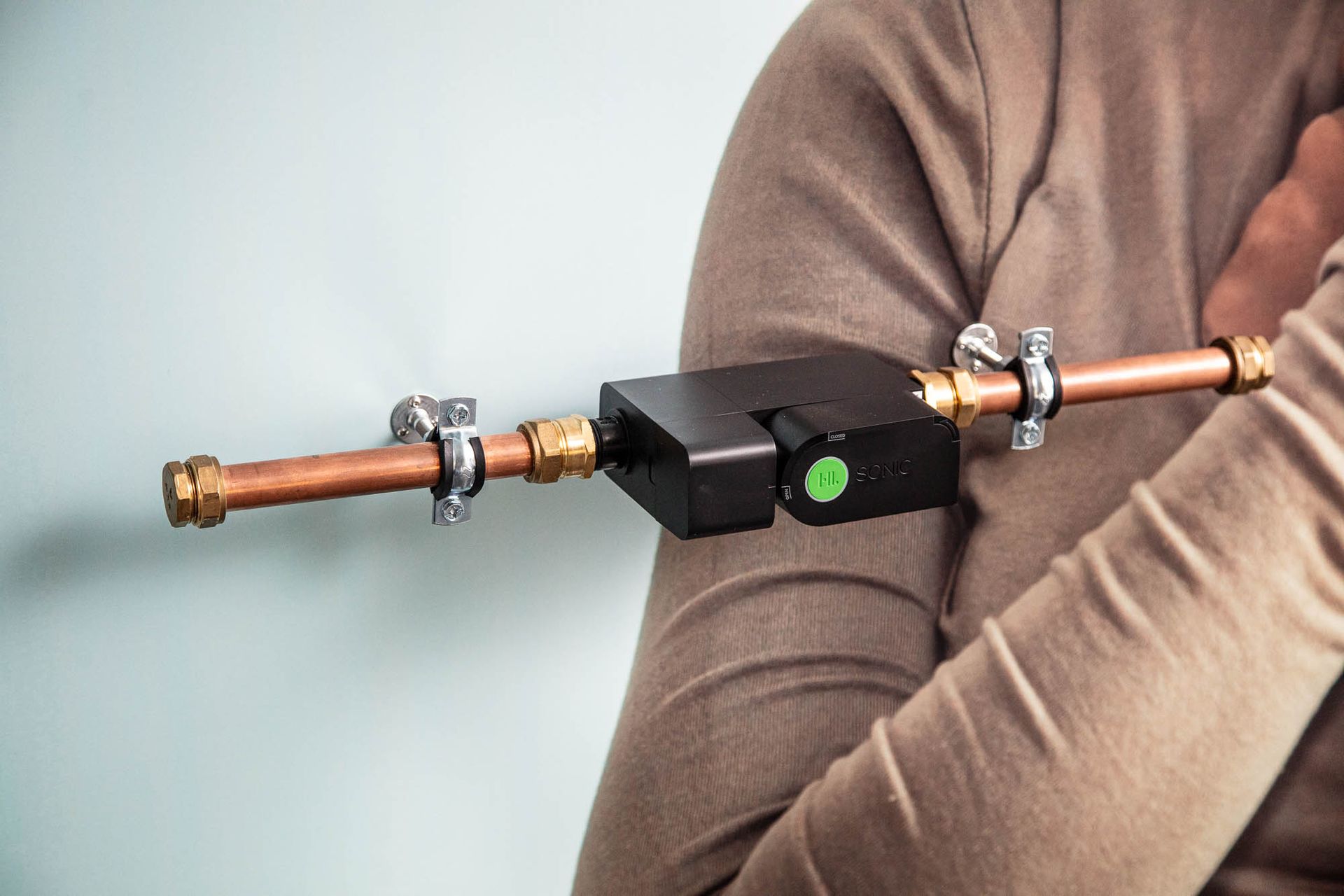
- Water Leak Sensor (Sonic now called Watergate water leak sensor – installed ‘dry’ i.e., not connected to an actual water pipe)
- Panic Button Pendant - GPS Enabled
- Smart Watch - GPS Enabled
- Hydration Monitoring Smart Mug
Healthcare Monitoring Service
- Connected Care Platform - Alerting Service, Dashboard of Health Insights & Reports
Book a Free of Charge & No Obligation Initial Consultation
Use the form below to book a Free of Charge & No Obligation Initial Consultation...to discuss how we could help you with your specific project.
Note: Search for a suitable date and time. Next complete the relevant details in the form to provisionally book your consultation. We will then get in touch with you to confirm your consultation.
Click here to book using our online scheduling tool

View our other projects
Click the button below to visit the Portfolio section of our website to view our other projects